
Technical Specifications for Angular Lattice Steel Transmission Towers
Unpacking the Differences Between Self-Support Tower and Guyed Towers
October 11, 2025
6G Wireless Communication Steel Tower
November 11, 2025The Unyielding Sentinel: Technical Specifications for Angular Lattice Steel Transmission Towers
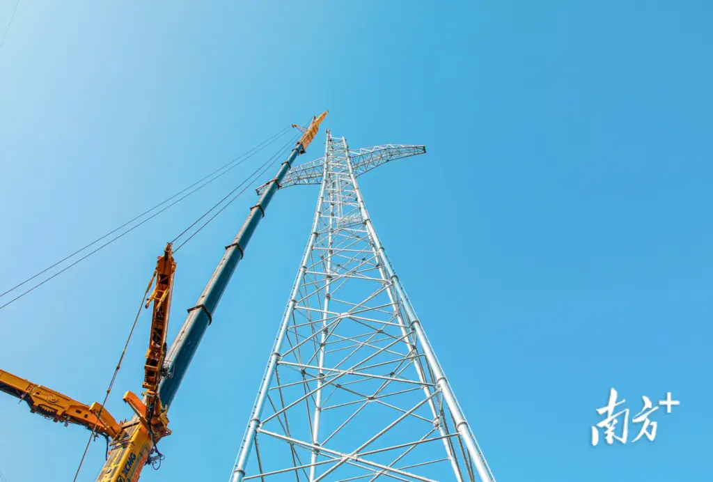
To gaze upon a massive transmission line and its supporting lattice towers is to witness a profound fusion of elemental physics and meticulous structural engineering. These angular sentinels, often stretching over $100 \text{ meters}$ into the sky, are the silent, unyielding infrastructure of global power grids. Their very existence is predicated on absolute reliability, a requirement so stringent that every dimension, every bolt, and every micron of surface coating is governed by an exhaustive set of criteria: the **Technical Specifications for Angular Lattice Steel Transmission Towers**This document is not merely a blueprint; it is a legal and engineering covenant that dictates the performance, material science, fabrication precision, and longevity of a structure designed to withstand nature’s fury while ensuring continuous power transmission.
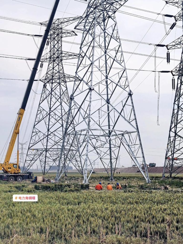
The mastery of the angle steel tower lies in its structural efficiency. It leverages the fundamental principles of the truss, resolving complex lateral and vertical forces into simple, purely axial stresses (tension or compression) within its constituent members. This methodology ensures maximum strength is achieved with minimal material mass, making it the most cost-effective and structurally transparent solution for high-voltage transmission lines. However, translating this elegant theory into a durable, functional reality requires adherence to technical conditions that touch upon metallurgy, advanced structural analysis, fabrication tolerance control, and specialized corrosion science. We must delve deep into these requirements, exploring the comprehensive specifications that ensure these towers remain unyielding in the face of extreme wind, severe icing, and relentless fatigue loading.
I. The Foundational Philosophy: Defining the Load Environment
The starting point for any rigorous set of technical conditions is the accurate definition of the operating environment—the world of forces the tower must withstand. This is not static; it is a dynamic symphony of environmental extremes, which must be synthesized into specific load cases. The specifications detail that the tower structure must maintain stability under several distinct, simultaneous loading combinations, often aligned with standards such as the Chinese DL/T 646 or international equivalents like IEC 60826 and ASCE/SEI 74.
Load Combinations and Reliability Factors
The technical conditions classify loads into categories, each paired with specific safety factors and probability metrics. The structural integrity is validated against scenarios far exceeding normal operation:
- **Normal Operating Load:** Static weight of the tower, conductors, insulators, plus everyday wind and temperature effects.
- **Heavy Wind Load:** The principal challenge, often defined by a $50$-year or $100$-year return period wind speed, applied dynamically across all members and conductors. The specifications dictate that the tower must manage the resulting massive overturning moments and lateral shear forces.
- **Extreme Ice Load:** In cold climates, the specifications demand calculation for the weight and increased wind profile due to radial ice accretion (e.g., $10 \text{ mm}$ to $40 \text{ mm}$ radial thickness). This load significantly increases vertical load and conductor tension, requiring robust foundation design.
- **Broken Wire Condition:** A critical asymmetric scenario where the failure of one or more conductors or ground wires creates a devastating longitudinal imbalance. The tower must resist this sudden, high, eccentric tension without progressive collapse, ensuring localized failure does not cascade across the transmission line.
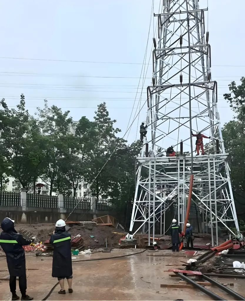
- **Construction and Maintenance Loads:** Accounting for temporary, concentrated loads from hoisting equipment, personnel, and working platforms.
The technical conditions stipulate that the analysis must be non-linear, accounting for the **P-Delta effects** (the amplification of moments due to axial load) and the secondary eccentricities inherent in a latticed structure. This detailed approach ensures that the design is based on the actual failure mode of the angle steel members—primarily **elastic and inelastic buckling**—rather than simple yield strength.
| Specification Parameter | Technical Requirement | Design Purpose |
|---|---|---|
| Reference Wind Speed ($V_{ref}$) | Defined by project site ($30 \text{ m/s}$ to $50 \text{ m/s}$ common) | Calculation of lateral wind pressure ($\text{kN/m}^2$) |
| Design Ice Thickness ($\delta$) | $0 \text{ mm}$ to $40 \text{ mm}$ radial (Zonal dependent) | Calculation of vertical load and increased wind area |
| Safety Factor ($\gamma_{t}$) | $\ge 1.1$ (Structure) to $\ge 1.5$ (Foundations) | Ensures reliability beyond calculated maximum load |
| Broken Wire Load Factor | $60\%$ to $70\%$ of maximum normal conductor tension | Prevents progressive collapse |
| Seismic Zone Compliance | Response Spectrum Analysis (for critical towers) | Resistance to ground motion and dynamic amplification |
II. Material Specification and Metallurgical Requirements: The Angle Steel Backbone
The very nature of the Angular Lattice Tower dictates the use of L-sections, and the technical conditions meticulously specify the quality of the steel to be used. These specifications move beyond simple yield strength, focusing heavily on chemical composition for **weldability** and the material’s **low-temperature toughness**—crucial for towers in northern latitudes.
The Spectrum of Structural Steel Grades
While historically, lower-strength grades (e.g., the Chinese Q235, comparable to S235 or A36) were dominant, modern technical conditions, driven by the desire for lighter, taller towers, mandate the use of high-strength, low-alloy (HSLA) steels. The primary modern grades specified are typically **Q345** and **Q420** (analogous to European S355 and S420). The numerical suffix indicates the minimum guaranteed yield strength in megapascals ($\text{MPa}$):
- **Q345 (Min. $345 \text{ MPa}$):** The workhorse for most tower members, offering an excellent balance of strength, weldability, and cost-efficiency. Its use allows for significant weight reduction over Q235, minimizing foundation costs and transportation expense.
- **Q420 (Min. $420 \text{ MPa}$):** Reserved for the heavily loaded main legs and base sections of ultra-high voltage (UHV) or extremely tall towers. Its use requires more stringent control over fabrication processes and potentially specialized welding procedures due to increased alloying content.
Chemical Requirements for Durability and Fabrication
The technical specifications are highly prescriptive regarding chemical limits, particularly for impurities that affect field fabrication and long-term durability. The **Carbon Equivalent ($\text{CE}$) must be strictly controlled**, especially for Q345 and Q420, to ensure that field welding (for maintenance or modifications) can be performed without excessive preheating and without forming brittle microstructures in the Heat Affected Zone (HAZ).
Furthermore, limits on **Phosphorus ($\text{P}$) and Sulfur ($\text{S}$)** are often tighter than minimum structural standards. High $\text{S}$ and $\text{P}$ content can promote lamellar tearing during heavy welding and reduce the steel’s toughness, which is unacceptable for a structure subjected to cyclic loads and impact events. Technical conditions usually mandate steel that has been produced via a controlled rolling or thermo-mechanical controlled process (TMCP) to achieve the required strength and fine grain structure, thus guaranteeing the minimum Charpy V-notch impact toughness requirements at low temperatures (e.g., $27 \text{ J}$ at $-20^\circ\text{C}$).
| Material Property | Q235 (Typical) | Q345 (Common Modern) | Q420 (High-Strength) |
|---|---|---|---|
| Minimum Yield Strength ($\sigma_{y}$) | $235 \text{ MPa}$ | $345 \text{ MPa}$ | $420 \text{ MPa}$ |
| Carbon Equivalent ($\text{CE}$) Max. | — | $\le 0.45$ | $\le 0.52$ (Tighter for thicker sections) |
| Sulfur ($\text{S}$) Max. | $0.045\%$ | $0.035\%$ | $0.035\%$ |
| Minimum Elongation ($\text{A}$) | $24\%$ | $21\%$ | $17\%$ |
III. Geometric Configuration and Structural Integrity: The Buckling Constraint
The technical specifications govern the structural arrangement and sizing of the lattice members, moving from the macroscopic arrangement of the cross-arms and tower body to the microscopic stability of each individual angle. The governing principle in an angle lattice tower is not tensile failure but **buckling instability** under compressive loads.
Slenderness Ratios and Effective Lengths
The performance of any compression member is defined by its **slenderness ratio ($\lambda$)**, the ratio of its effective buckling length to its radius of gyration. Technical conditions impose **maximum permissible slenderness ratios** for every class of member:
- **Leg Members (Main Load Bearing):** $\lambda_{max}$ is typically around $80$ to $120$. This strict limit ensures that the main legs possess sufficient stiffness to resist primary buckling and local distortion under the maximum calculated compressive load.
- **Main Bracing Members:** $\lambda_{max}$ is generally higher, perhaps up to $150$ to $200$. These members manage the transfer of shear loads, and while critical, they often experience greater load reversal (tension/compression).
- **Secondary Members (Redundancy and Stiffness):** $\lambda_{max}$ can be as high as $250$. These lighter members provide essential local stiffness to prevent the buckling of the larger members and support non-structural elements.
The specifications further detail the geometric constraints on the tower profile: the **taper ratio** of the tower body (how quickly the width decreases with height), the minimum width-to-height ratio for overall stability, and the clearance requirements for the conductors (mandating specific cross-arm lengths) to prevent flashovers under maximum sway. The goal is a structure optimized to fail simultaneously under its design load—meaning all major members reach their capacity limit at the same time—an indicator of perfect material efficiency and structural harmony.
IV. Manufacturing Precision and Fabrication Tolerance
The greatest divergence between theoretical design and field reality lies in fabrication. The technical conditions are relentless in prescribing tolerances because any deviation in member length or hole alignment can induce crippling secondary stresses in the final assembled tower, compromising its design capacity, particularly under compression.
Critical Tolerances for Assembly and Stress
The specifications detail the necessary precision for the thousands of components:
- **Member Length Tolerance:** For main members, this is extremely tight, often restricted to $\pm 1 \text{ mm}$ or $\pm 2 \text{ mm}$, irrespective of length. A leg member that is slightly too short forces its mating members into compression, creating residual stress before the operational loads are even applied.
- **Bolt Hole Alignment and Punching:** This is the most critical constraint. All bolt holes must be perfectly aligned across mating angle pieces. The tolerance for the distance between bolt holes (pitch) is typically restricted to $\pm 0.5 \text{ mm}$. The specifications often permit **punching** for holes up to $25 \text{ mm}$ in material up to $16 \text{ mm}$ thick, but mandate **drilling** for thicker sections or critical members to maintain material integrity and minimize stress concentrations around the hole edges.
- **Angle Straightness and Camber:** The specifications impose limits on the permissible sweep, camber, and twist in the angle members (e.g., maximum deviation of $1/1000$ of the member length). Excessive crookedness reduces the effective radius of gyration and drastically lowers the member’s buckling capacity.
The ultimate verification of fabrication precision is the **Shop Test Erection**. The technical conditions mandate that a certain percentage of the tower, typically the full base section and one complete body section, must be assembled in the factory before galvanization. This ensures $100\%$ bolt-hole matching and verifies the overall fit of the component sections, preventing costly and time-consuming modifications at the remote installation site.
| Tolerance Parameter | Requirement (Typical) | Engineering Rationale |
|---|---|---|
| Member Length | $\pm 1.5 \text{ mm}$ (Main Members) | Minimize residual stress in assembled tower |
| Bolt Hole Pitch (Center-to-Center) | $\pm 0.5 \text{ mm}$ | Ensure $100\%$ alignability for site assembly |
| Bolt Hole Diameter | Nominal bolt diameter $+ 1 \text{ mm}$ to $+ 2 \text{ mm}$ | Allows for minor erection adjustments |
| Angle Camber/Sweep | $\le 1/1000$ of member length | Maintain required slenderness ratio and buckling capacity |
| Face Width (Base) | $\pm 5 \text{ mm}$ | Ensure proper fit onto foundation anchor bolts |
V. The Essential Role of Connections: Bolting Specification and Pre-Tensioning
In a lattice tower, the connection points—the bolted joints—are the mechanical interfaces where stress concentrations are highest. The technical conditions are extremely stringent on the type and installation of the fasteners.
Fastener Grades and Pre-Tensioning
The specifications require the use of **High-Strength Structural Bolts**, typically conforming to grades **8.8** or **10.9** (metric), ensuring they possess the necessary shear and tensile capacity to manage the immense forces transferred between the angles. Bolts must be full-length, hot-dip galvanized and thread-matched to their nuts to prevent seizing (galling).
Crucially, the specifications define whether the connection is a **Bearing-Type** or a **Friction-Type** joint. Bearing joints (where the load is transferred by the bolt bearing against the hole wall) are common in many lattice bracing members. However, for critical leg-to-leg splices or cross-arm connections, **Friction-Type (Slip-Critical)** joints may be mandated. In these cases, the bolts must be installed to a specific, measurable **Pre-Tension** to ensure that the friction generated between the galvanized steel plates resists the design load, preventing any slip which could lead to fatigue failure or excessive tower movement.
Connection Plate Design
The gusset and splice plates used to join the angle members are also subject to tight specifications. They must be sized not only to transfer the maximum axial load but also to maintain the angle member’s geometric stiffness right up to the joint. Poorly designed connection plates can prematurely lower the buckling capacity of a main member. Furthermore, the number of bolts per connection is specified to provide redundancy, ensuring that the failure of a single bolt does not immediately lead to the failure of the entire joint.
VI. Corrosion Protection and Durability Specifications: The Galvanization Covenant
The specified service life of a transmission tower is often $50$ to $100$ years. Achieving this longevity in exposed environments—from corrosive industrial plumes to saline coastal air—relies almost entirely on the fidelity of the corrosion protection system, which, for angle steel towers, is **Hot-Dip Galvanization (HDG)**.
Zinc Coating Thickness and Adherence
The technical conditions mandate the standard for galvanization, often ISO 1461 or ASTM A123, but they usually impose **specific minimum average zinc coating thickness** based on the expected environmental severity. The coating thickness is measured in microns ($\mu\text{m}$) or grams per square meter ($\text{g/m}^2$).
- **Rural/Inland Environment:** $85 \mu\text{m}$ (minimum) is often sufficient, providing a corrosion life of 40-50 years.
- **Industrial/Coastal Environment:** $100 \mu\text{m}$ or higher may be specified, sometimes requiring a double-dip process or even a supplementary protective paint coating (a “duplex system”) to guarantee the required lifespan against high salinity or sulfuric acid pollutants.
The specifications require inspection of the galvanized layer for uniformity, adherence, and freedom from defects such as dross inclusion, bare spots, and excessive roughness. Adherence is typically checked via a hammering test or adhesion meter. Furthermore, all bolts, nuts, washers, and other fasteners must be galvanized to an equivalent or higher standard to prevent galvanic corrosion between the mating surfaces—a critical detail where zinc thickness is typically around $50 \mu\text{m}$ to $70 \mu\text{m}$.
VII. Quality Assurance, Testing, and Documentation: Proving the Sentinel’s Worth
The final layer of the technical conditions concerns the verification process—the systematic proof that the fabricated tower meets every design and material requirement. This process is exhaustive, ensuring traceability from the steel mill to the erected structure.
Material Certification and Dimensional Inspection
Fabricators must provide **Material Test Reports (MTRs)** for every heat of steel used, certifying the chemical composition and mechanical properties align with the specifications (e.g., Table 2). Every batch of bolts must also be accompanied by certification of their strength grade and galvanization thickness.
Dimensional checks are performed on a statistical sample of members to ensure compliance with the critical tolerances of Table 3. This is done using precision gauging and coordinate measuring machines (CMM) for complex splices. The documentation of these checks forms the foundation of the tower’s quality history.
The Ultimate Proof: Full-Scale Prototype Testing
For a new or complex tower design (e.g., $\pm 400 \text{ kV}$ towers or novel suspension towers), the technical specifications often culminate in the most demanding verification: **Full-Scale Prototype Testing**. A complete, representative tower structure is erected at a certified test station and subjected to increasing loads until it reaches and exceeds its design capacity in a controlled, destructive manner. This test validates the entire set of technical conditions—the accuracy of the structural analysis, the strength of the steel, the precision of the fabrication, and the integrity of the bolted connections—all under the most realistic load application possible. The technical conditions specify the exact load application points, the rate of loading, and the criteria for acceptable performance (e.g., no premature failure below $95\%$ of the ultimate design load).
| Requirement Category | Technical Condition | Verification Method |
|---|---|---|
| Material Traceability | Mandatory MTRs for all steel heats and bolts (Grade 8.8/10.9) | Documentation Review, Mill Audit |
| Galvanization Quality | Minimum average thickness (e.g., $85 \mu\text{m}$) | Magnetic Gauge Testing (Ferroscope), Adherence Test |
| Fabrication Fit-Up | $100\%$ bolt hole alignment tolerance | Shop Test Erection of Base Section |
| Structural Integrity | Resistance to ultimate design load | Full-Scale Prototype Test (for new designs) |
VIII. Conclusion: The Complexity of Simplicity
The Angular Lattice Steel Transmission Tower, seemingly simple in its angular geometry, is in reality an edifice of profound engineering complexity. The **Technical Specifications ** serve as the critical manual that ensures every component functions not just adequately, but perfectly, under the most hostile conditions. They transition seamlessly from the theoretical demands of high-velocity wind loads to the practical constraints of $\pm 0.5 \text{ mm}$ bolt hole pitch tolerance. The evolution from Q235 to Q420 steel is dictated by the specifications’ continuous quest for lighter, more efficient structures, while the strict galvanization requirements are the necessary promise of longevity. Ultimately, these technical conditions are the guarantor of the power grid’s resilience, transforming thousands of individual angle steel members into an unyielding sentinel that reliably delivers the lifeblood of modern society.