
High-Strength Steels in Transmission Tower Construction
February 13, 2026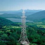
Dealing with Overweight 5G steel tower
February 20, 2026Steel Tower Design : A Field Engineer’s Guide to Selection and Design
Tower Talk: A Field Engineer’s Guide to Selection, Design, and Why Stuff Falls Down
Look, you can read all the glossy brochures from the manufacturers. You can run every finite element analysis package on the market until your workstation catches fire. But at the end of the day, putting a tower up—and keeping it up for twenty, thirty years—comes down to sweat, dirt, and a healthy dose of paranoia. They call me a Senior Structural Engineer now. Fancy title. But I still think of myself as the guy who has to sign the “as-built” drawings and then stand at the bottom of the thing while a crew winches up a 200-pound antenna in a 30-knot wind.
So, you want to know about tower selection and design for communication base stations? Good. Pull up a crate. Let’s talk.
This isn’t just about picking the tallest mast in the catalog. It’s a marriage between what the RF (Radio Frequency) planners want and what physics, the local zoning board, and your budget will allow. We are the referees in that fight.
The First Question: Self-Support, Guyed, or Monopole?
This is the first, and most important, fork in the road. It’s not just aesthetics; it’s about footprint, load, and cost. I’ve seen projects derailed because someone picked a pretty monopole when a utilitarian guyed tower was the only thing that could handle the wind load.
Here’s the breakdown, from my notebook:
| Tower Type | Typical Height Range | Pros | Cons | My Gut Feeling / Field Note |
|---|---|---|---|---|
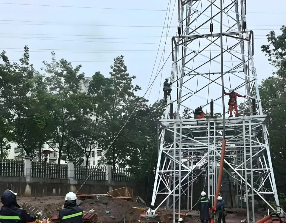
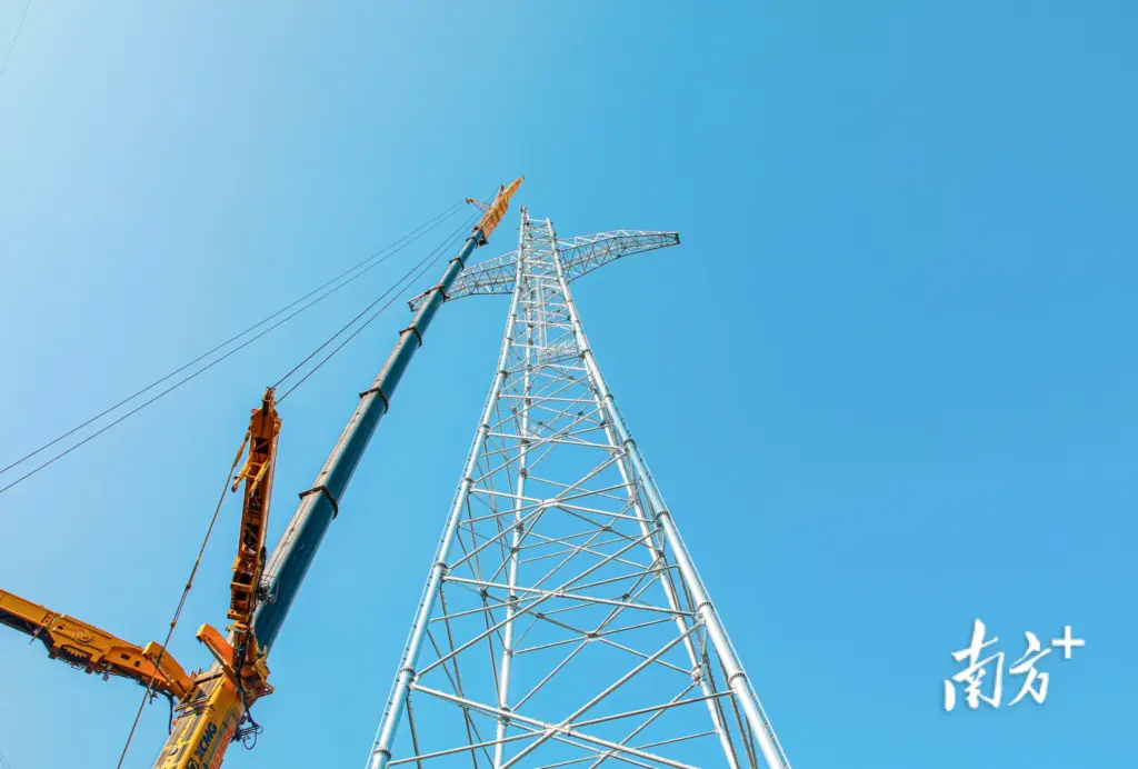
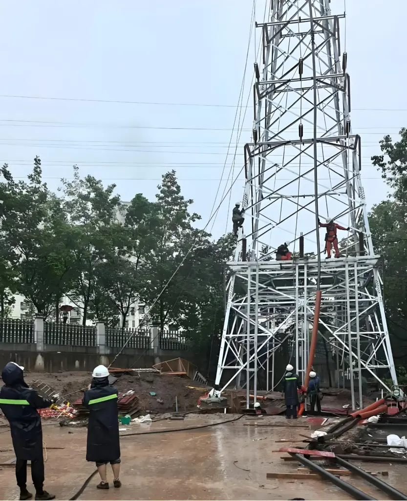
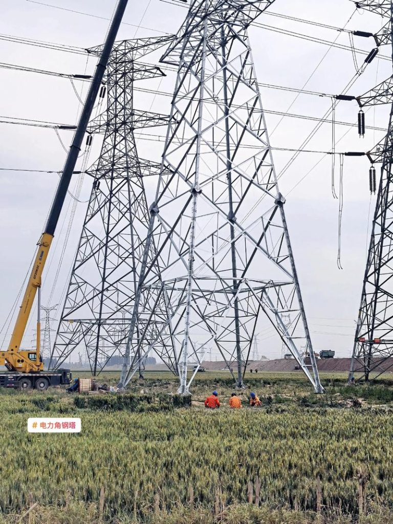
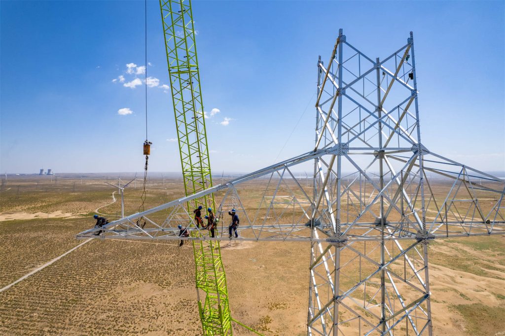
| Self-Supporting (Lattice) | 30m – 120m+ | High capacity, multiple tenants, relatively small footprint (3 or 4 legs). Stiff. | Higher material cost, requires more land than a monopole, visually imposing. | The workhorse of the industry. If you have the land and the budget, this is usually the most future-proof choice. We call them “four-poster beds.” |
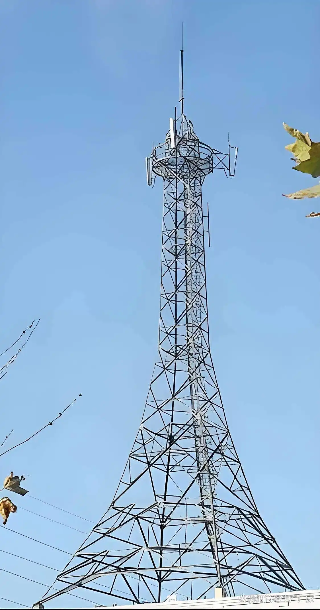
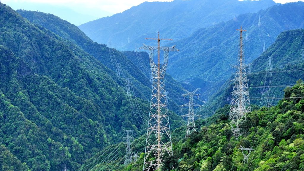
| Guyed Mast | 60m – 600m+ | Most economical for very tall heights, lightest weight. | Huge land footprint for guy anchors, prone to vandalism (climbing guys is a death wish), less stiff (more sway). | I have a love-hate relationship with these. They’re elegant solutions for broadcast or wide-area coverage. But I’ve also seen one come down in an ice storm because a guy wire failed. The anchor field is a sacred zone—keep the diggers away. |
| Monopole | 10m – 50m | Smallest footprint (great for urban), aesthetically preferred (“flagpole” style), quicker to install. | Limited capacity, higher deflection (sways more), difficult to climb internally (if hollow), foundation costs can be huge. | The urban warrior. Perfect for hiding in plain sight. But remember, that “flagpole” is a giant cantilever. All the force is transferred to one point in the ground. That concrete pier has to be absolutely perfect. |
Case in Point: A few years back, we were doing a site upgrade outside Austin for a major carrier. The site was a 120-ft monopole, already maxed out. The client wanted to add a massive new 5G mmWave panel and a bunch of remote radio heads. The wind load analysis came back red. Monopole was failing in deflection. The client threw a fit—they loved the small footprint. We ended up having to design a massive external cage and helical pier foundation to stiffen the base. Cost them three times what it would have if they’d just put up a skinny self-supporter from the start. They were focused on today’s problem, not next year’s.
The Devil in the Details: Design Parameters (The “Why”)
So, you’ve picked your tower type. Now we have to make sure it doesn’t fold like a cheap chair. This is where the engineering gets granular. We aren’t just drawing pretty pictures; we’re defining a set of rules for the wind, the ice, and the steel to follow.
1. The Loads: It’s Not Just the Tower’s Weight
We live by the formula: Total Load = Dead Load + Live Load + Environmental Load.
-
Dead Load (D): The weight of the tower itself. Simple, but not trivial.
-
Live Load (L): The stuff you put on it. Antennas, coaxial cables, waveguides, ice shields, ladders, platforms. I always add a fudge factor here. I call it “Future Tenant Fudge.” RF planners are optimists. They’ll tell you they’re putting up three antennas. In five years, they’ll have eight, plus a microwave dish pointed at a water tower. Design for expansion, or you’ll be back with a welding rig later.
-
Environmental Load (W for Wind, T for Ice): This is where we earn our money.
Wind load is governed by the classic formula:
F=qz∗G∗Cf∗Ae
Let’s break that down like we’re on site:
-
qz is the velocity pressure. It’s based on your basic wind speed (from local building codes, like ASCE 7 in the US), but modified for the height above ground and the exposure category. Is this tower in downtown Dallas (Exposure B with all the buildings) or out on the Kansas plains (Exposure C, with nothing to slow the wind)? Huge difference.
-
G is the gust effect factor. A stiff self-supporter handles a gust differently than a flexible monopole. We calculate this to account for the dynamic whip of the wind.
-
Cf is the force coefficient. Basically, the shape factor. A round monopole has a lower
Cf than a latticed angle-iron tower. Ice changes the shape completely—a round member becomes a flat plate for the wind to grab.
-
Ae is the projected area. The “sail area” of all those antennas and the tower itself.
Here’s a truth they don’t teach you: Ice is often scarier than wind. A 1/2-inch radial ice load can triple the effective area of your structural members and cables. Now the wind is acting on a much bigger, heavier, oddly shaped object. We have to check the tower for (a) the weight of the ice (Dead + Ice), and (b) the wind load on the iced-over structure. This combination often governs the design in the northern states. I did a job in Minnesota once where the code required a 1-inch ice load with concurrent wind. It was a beast.
2. The Foundation: Where the Rubber Meets the Road (Literally)
I don’t care how perfect your steel is; if the ground moves, your tower is scrap. We rely heavily on geotechnical reports. You can’t skip this.
For a standard 80-ft monopole, we might design a simple drilled pier with a base plate and leveling nuts.
Moverturning=Fwind∗Harm
That overturning moment at the base has to be resisted by the passive soil pressure on the pier and the weight of the concrete and soil plug. The formula for the required depth (d) is iterative, but it often boils down to an equilibrium of moments:
d≥3S∗b2.34∗Mo
Where
S is the allowable soil pressure and
b is the pier diameter.
For a big self-supporter, we’re talking massive spread footings or pile caps. Each leg sits on a huge block of concrete, tied together with grade beams. I saw a set of drawings once where the foundation design ignored the existence of a high water table. Six months after installation, one footing had settled six inches. The tower was visibly leaning. We had to underpin the whole damn thing with micro-piles. A $50,000 geotech report would have saved a $500,000 repair.
Material Selection: Steel Stories
We use steel. Specifically, we live in the world of ASTM A36 and A572 Grade 50. But not all steel is created equal.
-
Galvanizing is God. Hot-dip galvanizing per ASTM A123 is our religion. That zinc coating is the only thing standing between that beautiful tower and a pile of red dust. I inspect galvanizing like a hawk. Any bare spots, any “gray” patches where the zinc didn’t take? That’s a failure point in five years. I remember a supplier trying to save money by using “as-rolled” steel for bracing members on a coastal site in Florida. We rejected the whole shipment. The salt air would have eaten through it in a decade.
-
High-Strength Bolts. We use ASTM A325 or A490 bolts. And the installation is critical. You can’t just rattle them on with an impact gun until they squeak. There’s a tension specification. For A325 bolts, we use the “turn-of-nut” method. You snug them up, then give them a specific partial turn to induce the correct clamping force. A loose connection allows movement. Movement creates wear. Wear creates failure.
The “How to Solve Failure” Mindset
You can’t prevent all failures. But you can engineer for graceful degradation and catch problems early.
-
Redundancy: In a lattice tower, you have multiple load paths. If one diagonal brace fails, the other members can often redistribute the load temporarily. We design for this. A monopole has no redundancy. One crack, and it’s game over.
-
Connection Design: Failures almost always happen at connections. The weld between the leg and the gusset plate. The bolt group attaching the antenna mount to the pipe. We design connections to be stronger than the members they join. This is the “strong column-weak beam” philosophy applied to towers.
-
The Mount Point: This is my pet peeve. The pipe mount for the antenna. I’ve seen designs where a heavy antenna is cantilevered two meters off the tower leg on a thin-wall pipe. The dynamic leverage in a windstorm is insane. The bending moment at the base of that mount is:
M=Fantenna∗Larm
We need to check that mount for local buckling and the bolts for shear and tension simultaneously. It’s the most forgotten part of the design.
Latest Trends and a Glimpse at the Future
My tablet is full of notes from recent conferences and projects. Here’s what’s on my mind right now:
-
5G is a Weight Problem: Those new Active Antenna Units (AAUs) are heavy. They combine the antenna and the radio into one box. And they’re big. We’re seeing sites where the planned equipment load has doubled overnight. We’re having to re-rate thousands of existing towers. The industry is scrambling.
-
Concealed Architecture: Cities are getting tougher. We’re doing more “mono-palm” trees (hideous, in my opinion) and “church steeple” hides. It’s an interesting design challenge—how to maintain structural integrity while making it look like a tree trunk or a brick chimney.
-
Digital Twins & AI Monitoring: We’re starting to put sensors on critical towers—strain gauges, accelerometers, inclinometers. This creates a “digital twin.” We can see how the tower behaves in a real storm and compare it to our models. We had a project in Chicago where we instrumented a tall, slender tower. The real-world deflection matched our model within 2%. That was a good day. It tells us our assumptions are correct.
-
Material Science: I’m seeing more talk about high-performance steel and even glass-fiber-reinforced polymer (GFRP) for platforms and ladders. It doesn’t rust. It’s non-conductive. But can it take the UV and the cold? Time will tell.
A Final Word on Reliability (Trustworthiness)
You want a reliable tower? Pay for the inspection. Not just the design, but the construction inspection.
-
Bolt Torque: I’ve seen crews leave bolts finger-tight. We do random torque checks.
-
Plumbness: After erection, we climb it and check it with a theodolite. It should be within 1:500 (for every 500 feet of height, it can be off by 1 foot). If it’s leaning more than that, something is wrong with the foundation or the initial assembly.
-
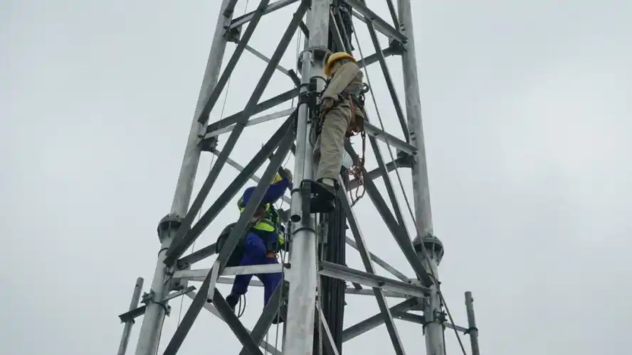
The First Climb: The most honest test. I climb every tower I design, at least for the first few years of my career. You feel the vibration. You see the connections up close. You hear the wind in the guys. It’s a perspective you can’t get from a computer screen.
So, that’s the long and short of it. Tower design isn’t magic. It’s a careful, paranoid, and experienced-based application of physics and material science. It’s about asking “what if” until you run out of answers. Because when you’re 200 feet up, bolting on a million-dollar piece of equipment, the last thing you want to wonder is if the guy in the office did his math right. You want to know he did. And that’s the trust we build, one connection at a time.
