
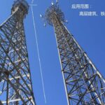
Angular Steel Towers for Communication
Communication Towers Q355 Steel VS Q390/Q420 Steel
March 4, 2026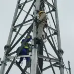
Transmission Tower Inclination Rectification: In-situ Reinforcement and Jacking Technologies
March 22, 2026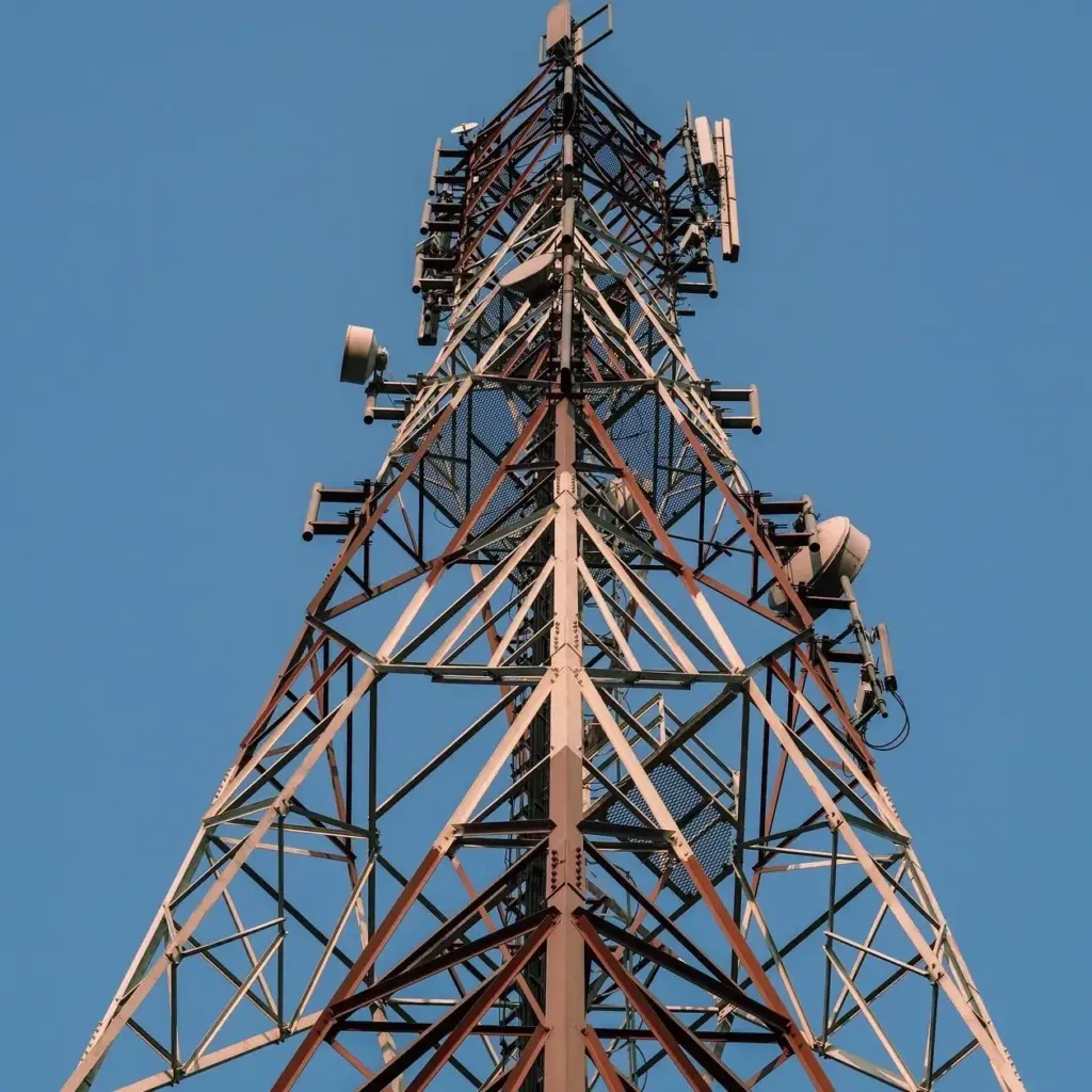
The Unspoken Truth About Angular Steel Towers: What the Spec Sheets Won’t Tell You
Look, I’ve been in this industry for twenty-three years. Started as a welder’s apprentice back in 2001, worked my way up through quality control, site supervision, and now I’m the guy clients call when their “perfectly designed” tower starts swaying more than it should. I’ve erected towers in the freezing winds of Inner Mongolia, the corrosive salt spray of Hainan coast, and the unstable soils of Southeast Asia. So when someone asks me about angular steel towers, I don’t pull out the marketing brochure. I tell them what actually matters.
Before We Get Into The Weeds: Why Angular Steel?
You’re probably reading this because somewhere along the line, someone told you that angular steel towers are the workhorses of the telecommunications industry. They weren’t wrong. But here’s the thing—when I started out, we used a lot more tubular towers. Still do, for certain applications. But angular steel? There’s a reason it’s been the go-to choice for decades, and it’s not just because it’s cheaper.
The math is actually pretty elegant. Take a piece of angle steel—say a 100x100x10 section. The way the forces distribute through that L-shaped profile gives you tremendous strength-to-weight ratio. The moment of inertia about the principal axes allows the structure to handle eccentric loading from antennas in ways that simple sections just can’t match.
But I’m getting ahead of myself.
What Exactly Are We Talking About Here?
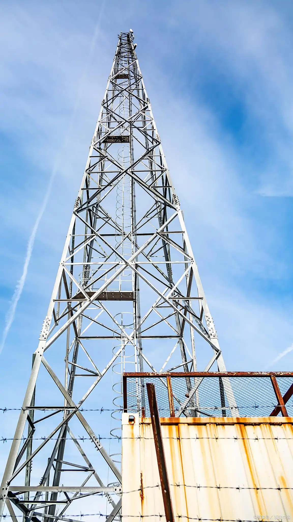
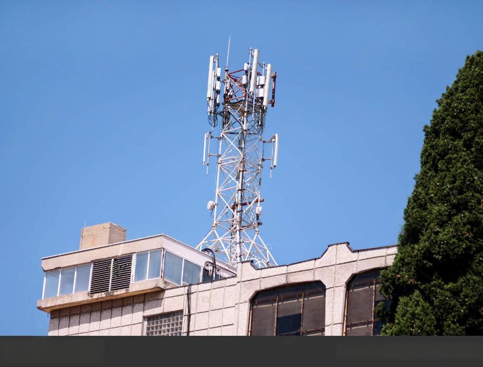
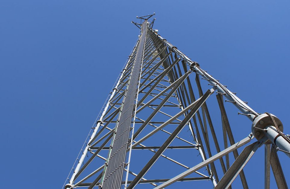
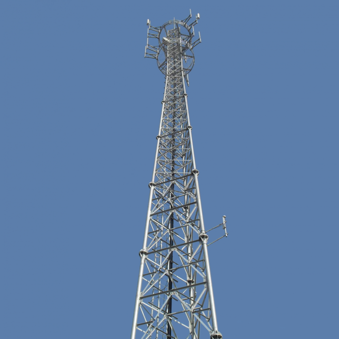
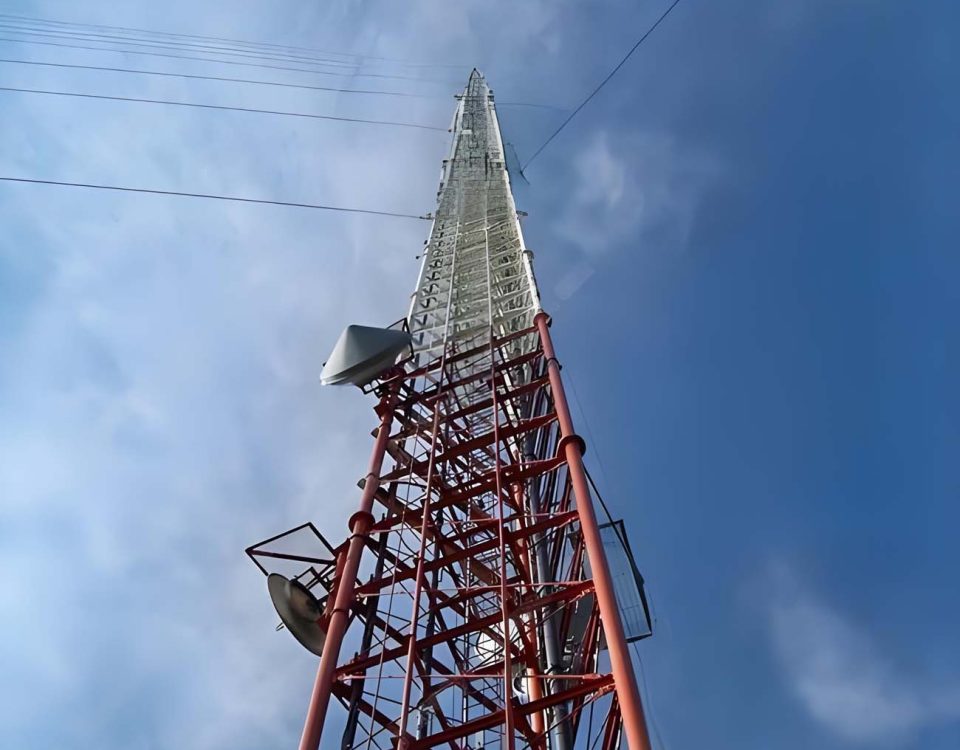
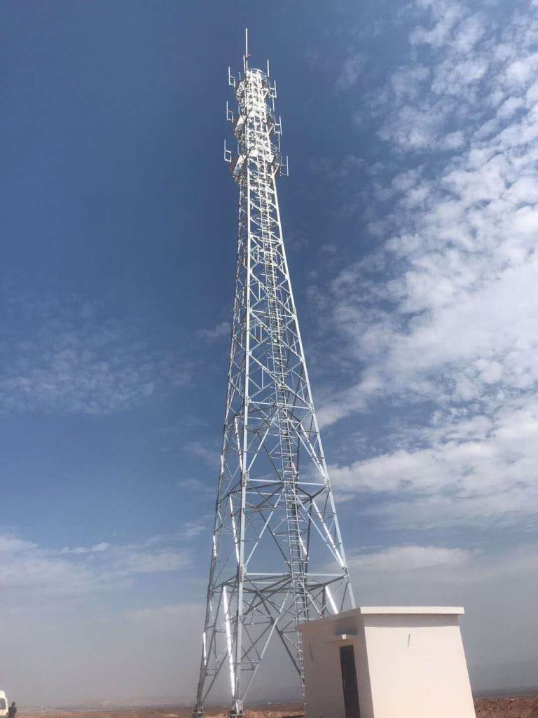
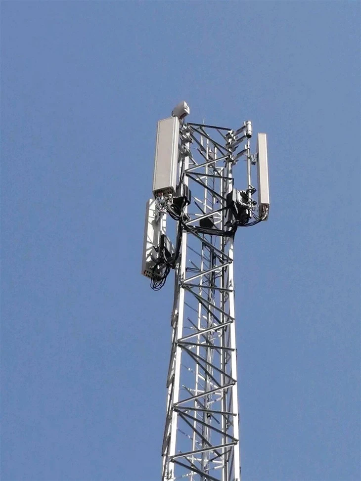
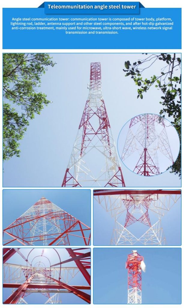
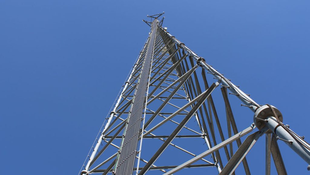
An angular steel communication tower is exactly what it sounds like—a lattice structure fabricated from hot-rolled angle sections and steel plates. We’re not talking about pretty, streamlined monopoles you see in city centers. These are utilitarian structures, designed for one purpose: getting antennas up high enough to do their job and keeping them there, regardless of what weather throws at them.
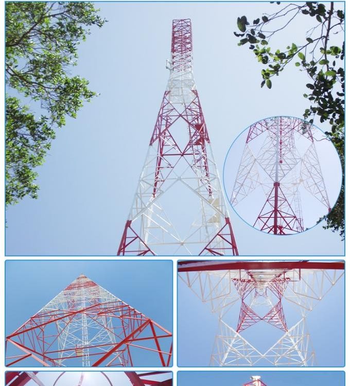
The configuration is usually triangular or square in cross-section—three-leg or four-leg designs, depending on height requirements and available real estate. Three-leg towers use less material, weigh less, and cast a smaller footprint. Four-leg towers? They’re stiffer, can handle heavier antenna loads, and give you more options for equipment mounting.
Table 1: Common Angular Steel Tower Configurations
| Leg Configuration | Typical Height Range | Typical Base Width | Typical Top Width | Primary Application |
|---|---|---|---|---|
| 3-leg | 15m – 60m | 3m – 8m | 0.5m – 1.2m | Rural coverage, microwave links |
| 3-leg (heavy) | 45m – 90m | 6m – 12m | 0.8m – 1.5m | Regional coverage, broadcast |
| 4-leg | 30m – 100m+ | 4m – 15m | 1.2m – 2.5m | Urban infill, heavy antenna loads |
| 4-leg (heavy) | 60m – 120m+ | 8m – 20m | 1.5m – 3.0m | Broadcast, backbone microwave |
Now you’ll see material specifications such as Q235B, Q345B, Q355B (Q355B is actually replacing Q345B according to the new GB standard), ASTM A572 Grade 50, or S355JR under the EN standard—these are not simply a combination of letters. Each specification has its specific yield strength, weldability, and performance over different temperature ranges.
Q235B gives you yield strength of 235 MPa minimum. Good for lighter structures, secondary members, or applications where you’re not pushing the envelope. Q345B/Q355B bumps that up to 345 MPa minimum—that’s your workhorse material for main legs and critical bracing. But here’s something the spec sheets won’t tell you: the transition from Q345B to Q355B under the new GB/T 1591-2018 standard isn’t just a number change. The chemistry’s different—lower carbon equivalent, better weldability, improved toughness. If you’re still specifying Q345B on new projects, you’re working with outdated standards.
The Real Talk: What Keeps Procurement Managers Awake at Night
I’ve sat across the table from dozens of procurement managers and project directors. After the pleasantries, after the tea, after they’ve asked about delivery times and pricing—that’s when the real questions come out. And they all circle back to the same few fears.
Fear #1: “Will This Thing Fall Down When I’m Not Looking?”
And they don’t mean collapse catastrophically—though that happens too, more often than the industry likes to admit. They mean progressive deterioration. Corrosion eating away at critical connections. Fatigue cracks starting at weld toes. Foundation settlement throwing the whole structure out of plumb.
Here’s how we address it.
The galvanizing isn’t just a coating—it’s a metallurgical bond. When we hot-dip galvanize to GB/T 13912-2002 or ASTM A123, we’re creating zinc-iron alloy layers that, if properly applied, will outlast the design life of the structure. I’ve taken cores from 40-year-old towers where the galvanizing was still intact. But—and this is a big but—it depends entirely on surface preparation and bath chemistry.
Table 2: Galvanizing Thickness Requirements by Standard
| Standard | Minimum Average Coating Thickness | Steel Thickness Range | Test Method |
|---|---|---|---|
| GB/T 13912-2002 | 70 μm | >6 mm | Magnetic gauge |
| ASTM A123 | 3.9 mils (100 μm) | >6 mm | Magnetic gauge |
| EN ISO 1461 | 85 μm | >6 mm | Magnetic gauge |
| AS/NZS 4680 | 100 μm | >6 mm | Magnetic gauge |
But here’s the kicker—thickness isn’t everything. I’ve seen beautifully thick galvanizing fail because the fabricator didn’t vent the sections properly, leaving trapped acid from the pickling process that eventually worked its way out and started corroding from the inside. The solution? Proper detailing. Every closed section needs vent holes. Every overlapping surface needs to be sealed or designed to allow galvanizing penetration.
And for the welds? AWS D1.1 is the gold standard, but the standard only gets you so far. I’ve watched welders who could pass any certification test lay down beautiful beads that looked perfect—until you x-rayed them and found lack of fusion at the root. The real protection comes from weld procedures that account for the actual position the welding will be done in, not just the ideal lab conditions.
Fear #2: “The Wind’s Going to Take It Down During the First Big Storm”
This fear is real, and it should be. I’ve done failure analysis on three wind-toppled towers in my career. Every single one of them had been “designed to code.” So what went wrong?
Wind loading isn’t static, and it isn’t simple. When we design to TIA-222-G (still widely used, though H is current now), we’re accounting for wind speeds, exposure categories, topographic effects, and—critically—ice loads in some regions. But the math only gets you partway.
The formula for wind force on a tower section looks something like this:
Where:
- $q_z$ is the velocity pressure at height z
- $G$ is the gust effect factor
- $C_f$ is the force coefficient
- $A_e$ is the projected area
But here’s what the formula doesn’t show: the force coefficient for angular sections is different from tubular sections. The flat surfaces create more drag, but they also create different flow patterns. In certain wind directions, an angular tower can actually see higher local loads on individual members than the overall analysis predicts.
Table 3: Force Coefficients for Lattice Towers (TIA-222-G)
| Tower Face Configuration | $C_f$ for Square Towers | $C_f$ for Triangular Towers |
|---|---|---|
| Flat-sided members | 3.2 – 4.0 | 2.4 – 3.2 |
| Round members (all) | 2.0 – 3.2 | 1.6 – 2.4 |
| Mixed construction | 2.4 – 3.6 | 2.0 – 3.0 |
The solution isn’t just running the numbers once. It’s understanding the assumptions behind those numbers. When we design for 180 km/h winds (3-second gust), we’re talking about a wind pressure of approximately:
That’s about 156 kg per square meter of projected area. But that’s at reference height. Multiply by exposure factors, gust factors, and you’re easily looking at 300+ kg/m² at the top of a tall tower.
Fear #3: “The Foundation’s Going to Sink or Tilt”
I’ve seen this more times than I care to count. Beautiful tower, perfect fabrication, excellent welding—sitting on a foundation that was never right for the soil conditions.
The foundation design isn’t just something you pull out of a standard table. Sure, we have typical designs for “normal” soil—2-3 meters deep, reinforced concrete pad and pedestal, holding down anchor bolts that are 1.5 to 2.5 meters long, 36mm to 64mm diameter depending on the tower. But “normal” soil doesn’t exist in many places I’ve worked.
Take the project we did in Zhanjiang back in 2019. Soil report showed clay, but nobody told us it was expansive clay—the kind that swells when wet and shrinks when dry. Within six months of installation, the tower was 45mm out of plumb. The fix? Underpinning the foundation with friction piles that went down to the stable layer 12 meters below. Cost the client triple what they’d budgeted.
Now we do a simple swell test on any clay site. If the plasticity index is above 25, we’re either going to deep foundations or we’re replacing the entire soil column under the foundation with granular material.
Table 4: Typical Foundation Parameters by Soil Type

| Soil Type | Bearing Capacity (kPa) | Typical Pad Size (4-leg, 40m) | Anchor Bolt Embedment | Special Considerations |
|---|---|---|---|---|
| Rock | 500+ | 2.5m x 2.5m x 0.8m | 1.2m – 1.5m | Minimal reinforcement needed |
| Dense gravel | 300-400 | 3.5m x 3.5m x 1.0m | 1.8m – 2.2m | Good drainage critical |
| Stiff clay | 200-300 | 4.0m x 4.0m x 1.2m | 2.0m – 2.5m | Check for shrink-swell |
| Loose sand | 100-150 | 5.0m x 5.0m x 1.5m | 2.5m – 3.0m | Compaction or piles needed |
| Soft clay | 50-100 | Pile cap | Piles to 8m+ | Geotechnical investigation mandatory |
Fear #4: “The Installation Crew’s Going to Mess It Up”
This fear is well-founded, because installation is where most of the problems that aren’t design problems actually happen.
I watched a crew in Cambodia try to erect a 60-meter tower with a crane that was 10 tonnes under capacity because the project manager was trying to save money on equipment rental. They got the tower halfway up, the crane started tipping, and they had to do an emergency lowering that bent half the bracing members.
The math for crane selection isn’t complicated, but people ignore it:
But the “total weight” isn’t just the steel. It’s the rigging, the lifting lugs, the temporary bracing. And the safety factor? For critical lifts, we use 1.5 minimum. That means if your heaviest section weighs 5 tonnes, you need a crane rated for 7.5 tonnes at that radius. And the radius matters—crane capacity drops off fast as the boom extends and the load moves away from the center of rotation.
Fear #5: “The Bolts Are Going to Loosen Over Time”
Bolted connections are both the beauty and the curse of angular steel towers. They make erection possible, allow for disassembly if needed, and create predictable load paths. But they also introduce the risk of loosening.
Every bolt in a tower should be tensioned to a specific torque:
Where:
- $T$ is torque (N·m)
- $K$ is the nut factor (typically 0.15-0.20 for galvanized surfaces)
- $D$ is bolt diameter (mm)
- $P$ is desired preload (N)
For a Grade 8.8 M20 bolt, we’re typically looking at preload around 125 kN, which gives a torque of:
But here’s the thing—torque wrenches need calibration, and I’ve seen sites where the “calibrated” torque wrench hadn’t seen a calibration lab in five years. The result? Bolts either undertorqued (loosen over time) or overtorqued (yield or break).
Table 5: Bolt Specifications for Angular Steel Towers
| Bolt Grade | Yield Strength (MPa) | Tensile Strength (MPa) | Typical Application | Installation Torque (M20) |
|---|---|---|---|---|
| 4.6 | 240 | 400 | Secondary bracing | 210 N·m |
| 5.6 | 300 | 500 | General connections | 260 N·m |
| 6.8 | 480 | 600 | Main members | 320 N·m |
| 8.8 | 640 | 800 | Critical connections | 425 N·m |
| 10.9 | 900 | 1000 | Special high-strength | 550 N·m |
The solution isn’t just better torque control. It’s understanding that galvanized surfaces have different friction characteristics than clean steel. That nut factor K changes with lubrication, surface finish, even humidity. We’ve started requiring that all critical connections use direct tension indicators—those little domed washers that flatten when the right tension is achieved.
The Application Side: Where Do These Towers Actually Go?
Mobile Communications
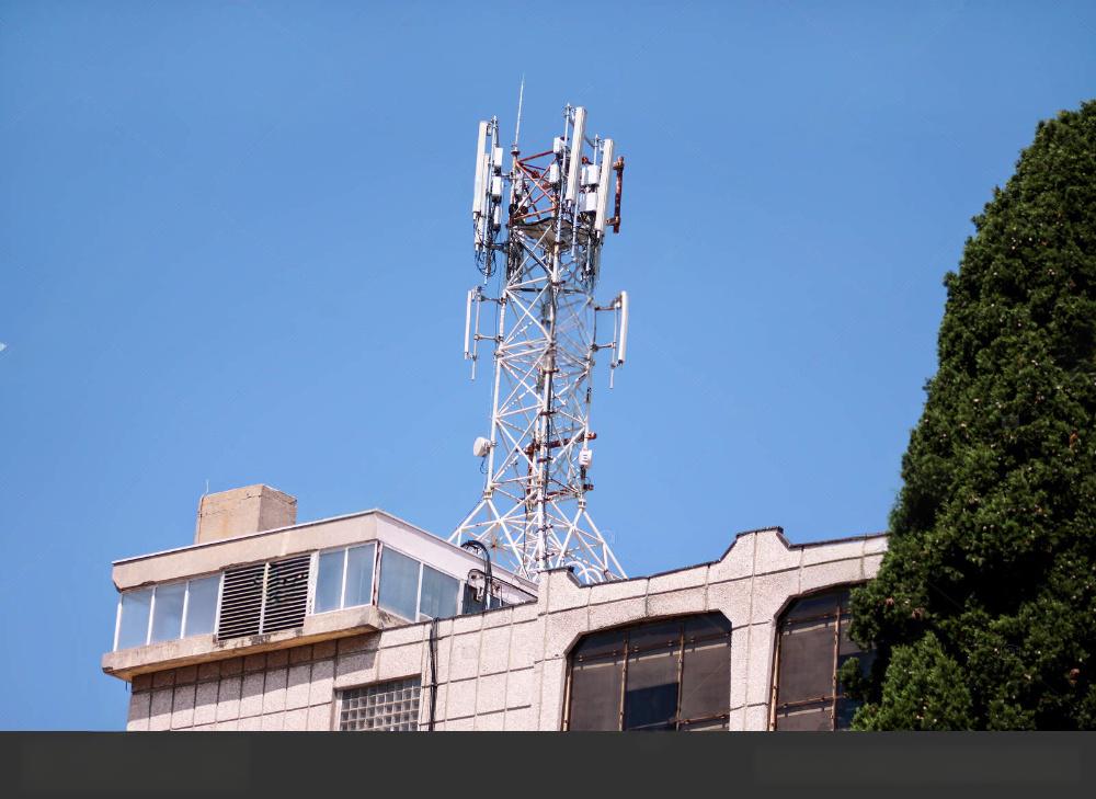
The bread and butter of the industry. Every GSM, CDMA, 3G, 4G, and now 5G network relies on towers. But the requirements have changed. With 5G, we’re seeing more equipment at lower heights—small cells, distributed antenna systems. But the macro coverage still needs height, and angular steel towers still provide the most cost-effective solution for rural and suburban coverage.
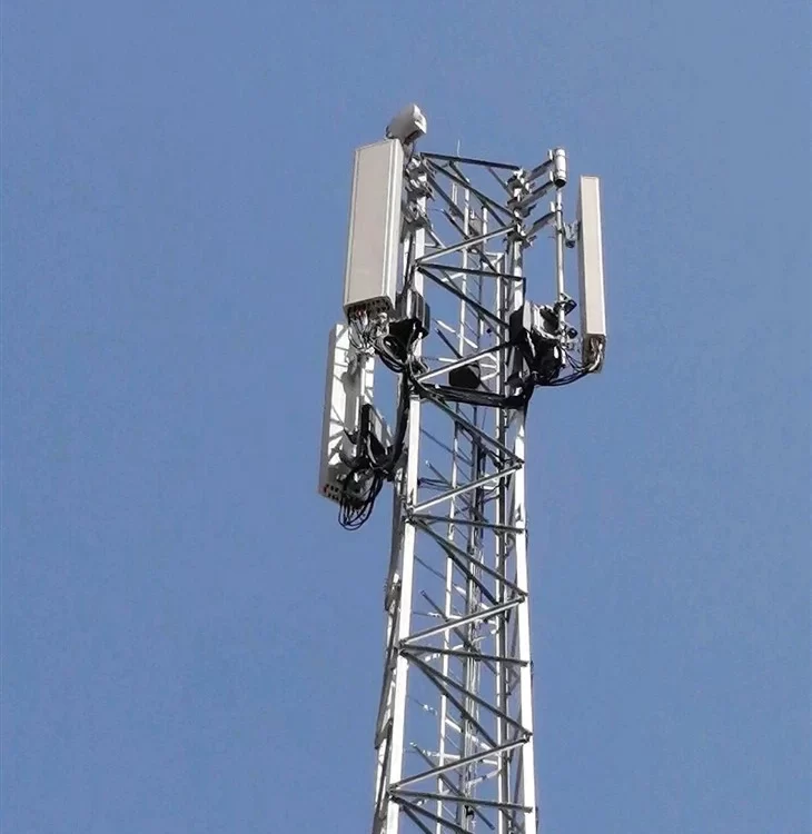
The antenna configurations have gotten more complex. It used to be one or two antennas per operator. Now we’re seeing multiple arrays, remote radio units (RRUs) mounted right at the antenna, GPS receivers, microwave dishes for backhaul. A typical configuration on a 50-meter tower might include:
- 6 panel antennas (three sectors, two frequencies)
- 6 RRUs
- 2 GPS antennas
- 2 microwave dishes
- 1 lightning rod
- Cable ladders and mounting frames
All of that adds wind load. A single panel antenna can have a projected area of 0.5-1.0 m². Multiply by 6, add the dishes, add the mounting steel, and you’re looking at 10-15 m² of additional area that wasn’t in the original design. This is why we design with future loading in mind—20-30% spare capacity is standard practice for anyone who’s been burned by having to reinforce a tower after five years.
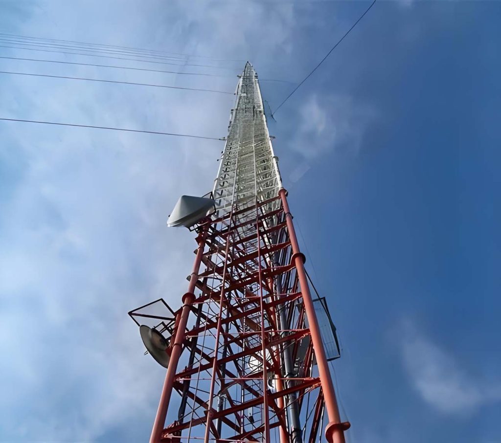
Broadcasting
TV and radio broadcasting is a different beast. The antennas are bigger, heavier, and often top-mounted rather than side-mounted. A typical FM broadcast antenna might be 6-8 meters tall, weighing 500-1000 kg, with a wind load that’s essentially a point load at the very top of the tower.
The math for top-mounted antennas is unforgiving:
The moment at the base increases linearly with height. A 60-meter tower with a heavy top antenna sees almost all its base moment from that antenna, not from the tower itself.
Microwave Communications
Microwave links have their own special requirements. The dishes need clear line of sight, which means they need to be high enough to clear obstacles. But they also need pointing accuracy that doesn’t change with wind or temperature. The verticality requirement for microwave towers is often tighter than for cellular—<1/1000 is typical, but some links need 1/2000 or better.
The relationship between tower deflection and signal loss isn’t linear:
When a tower twists or sways, the pointing error can turn a strong signal into static. I’ve seen microwave links go down because a tower deflected 0.5 degrees in a moderate wind—well within structural limits, but disastrous for the link budget.
What’s Changed in Recent Years
The industry doesn’t stand still. Here are three trends I’m seeing right now that are changing how we design and build angular steel towers.
Trend 1: The Shift to Q355B
China’s GB standards updated in 2018, replacing Q345 with Q355. The numbers matter—355 MPa minimum yield instead of 345. Small change, but it reflects improvements in steelmaking. The more important change is in the carbon equivalent formula:
The new standard requires lower CEV for better weldability. That means less preheat required, less risk of hydrogen cracking, faster fabrication. If your fabricator is still using old-stock Q345, ask why.
Trend 2: Digital Twin Integration
We’re starting to see requirements for digital models that go beyond the design phase. Clients want a model they can use for maintenance planning, for antenna additions, for structural assessment years down the road. The old approach—as-built drawings in a binder that gets lost—is dying.
For a 60-meter angular tower, the digital twin might include:
- Actual as-built member sizes (not just design sizes)
- Weld inspection records linked to specific joints
- Bolt torque records by connection
- Galvanizing thickness measurements by zone
- Foundation concrete test results
Trend 3: Sustainability Requirements
Green building standards are starting to affect tower procurement. Questions about recycled content, about coating systems, about end-of-life recyclability. Angular steel towers score well here—steel is infinitely recyclable, galvanizing doesn’t prevent recycling, and the bolted construction means they can be disassembled rather than demolished.
The Hidden Costs Nobody Talks About
Let me tell you about a project in northern Vietnam. We bid on a 70-meter angular tower, won the contract, fabricated, shipped, installed. Everything went perfectly. Then the client asked for the maintenance manual.
We sent our standard manual—inspection intervals, torque checks, corrosion monitoring, foundation settlement markers. The client’s maintenance team looked at it and said, “We can’t read this. It’s in English.”
So we had to translate. Then retranslate when the first translation was inaccurate. Then fly a technician out to train the local team because the translated manual still wasn’t clear. Added 15% to our costs and two months to the schedule.
The lesson? Maintenance requirements matter as much as design requirements. If your tower’s going somewhere with non-English speakers, you need documentation in the local language, and you need training that accounts for local skill levels.
Table 6: Maintenance Requirements by Component
| Component | Inspection Frequency | Common Issues | Remedial Action |
|---|---|---|---|
| Bolted connections | Annually (visual), 5 years (torque check) | Loosening, corrosion | Retorque, replace if corroded |
| Galvanized surfaces | Annually | White rust, dark spots | Clean, apply zinc-rich paint |
| Welds | 5 years (visual), 10 years (NDT) | Cracking, corrosion | Grind, repair weld |
| Foundation | Annually (visual), 5 years (survey) | Settlement, cracking | Monitor, underpin if active |
| Antenna mounts | Annually | Corrosion, loose bolts | Retorque, replace if corroded |
| Lightning protection | Annually | Corroded connections, broken conductors | Clean connections, replace conductors |
Real-World Case: The 90-Meter Coastal Tower
In 2022, we completed a 90-meter angular steel tower for a broadcast client in Fujian province, about 2 kilometers from the coast. The site selection was non-negotiable—had to cover a specific valley and the coastal waters beyond.
The challenges:
- Salt spray exposure (corrosion category C5 according to ISO 12944)
- Typhoon winds (designed for 200 km/h, 3-second gust)
- Soft soil (alluvial deposits 30 meters deep)
- Limited access (narrow roads through fishing villages)
The solutions:
- Enhanced galvanizing (minimum 120 μm, with sealed overlap joints)
- 对特定晶格构型进行风洞试验
- Driven steel piles to 25 meters depth, with cathodic protection
- Modular fabrication (3-meter sections, max weight 4 tonnes)
The tower’s been operational for 18 months now. We’ve got corrosion monitoring coupons installed at various heights, and the initial readings show corrosion rates well below predicted. The foundation settlement? Less than 5mm after one year. The wind monitoring system has recorded gusts to 150 km/h with no significant deflection.
But here’s what the spec sheet doesn’t show: the local fishermen use the tower as a landmark. They painted a red stripe around the base at the 5-meter level—something about their boats, their navigation, their tradition. We didn’t specify that. The client didn’t ask for it. But it happened, and now that tower is part of the community.
Procurement Decisions: What Actually Matters
If you’re reading this because you’re about to buy an angular steel tower, here’s what I’d tell you:
Don’t buy on price alone. The difference between a good tower and a bad tower isn’t in the steel grade—it’s in the details. The quality of the welding. The accuracy of the drilling. The care in galvanizing. The completeness of the documentation.
Visit the fab shop. If you can’t visit, get a video tour. Look at how they store material. Look at their welding booths. Look at their quality control station. A clean, organized shop produces better towers than a messy one, full stop.
Ask their assemblers. Welders always get the most attention, but the assemblers who lay the steel and do spot welding before welding—they’re just as important. A good assembler makes the welder’s job much easier, while a bad assembler makes the job impossible.
Check references. But don’t just call the references they give you. Ask for projects from five years ago, not last year. A tower that’s stood for five years without problems tells you more than a tower that’s been up for six months.
Understand the logistics. A 60-meter tower breaks down into maybe 20-30 pieces for shipping. How are those pieces packaged? How are they marked? I’ve seen shipments arrive with the steel in perfect condition but the marking tags washed off by rain, leaving the erection crew playing guessing games with 50 tonnes of steel.
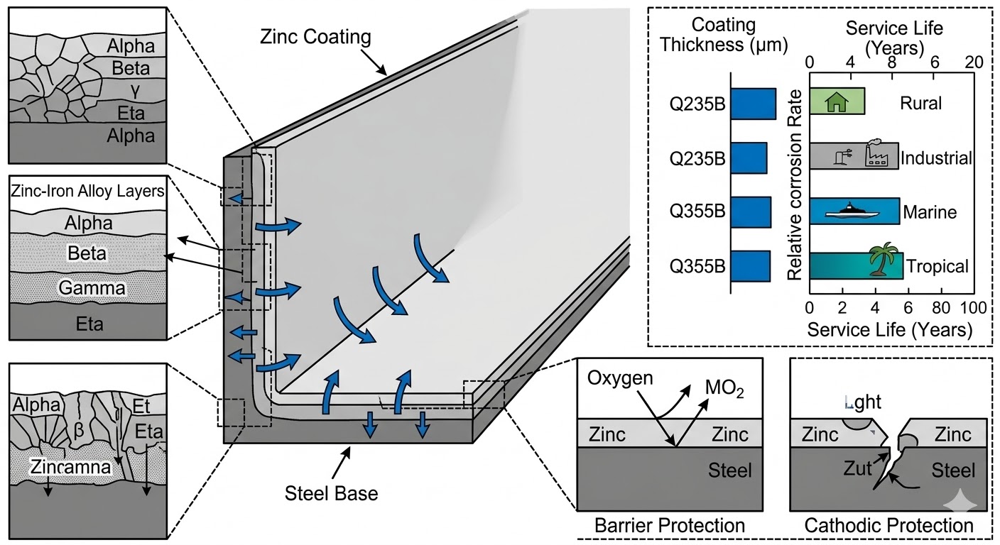
First chart: Material & Environmental Condition Analysis
This image will show the microstructure of the hot-dip galvanized layer on the surface of angle steel, as well as its anti-corrosion mechanism and protective effect in outdoor atmospheric and salt spray environments.
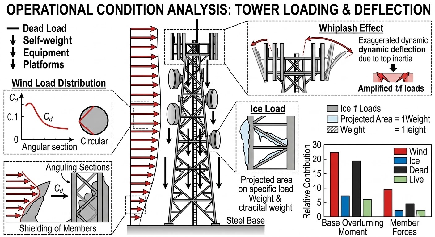
Second diagram: Structural Operational Condition Analysis of the tower
This diagram will show how the various complex loads on the communication tower are distributed and act on the tower, including dead load (self-weight, antenna), live load (maintenance), and most critical environmental loads (wind load, ice load).
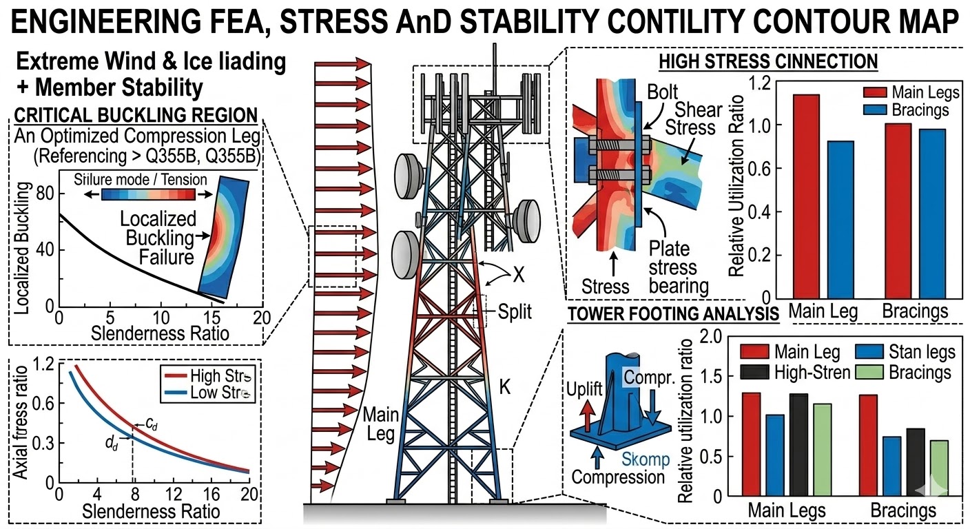
Third chart: Mechanical Performance & Stress Analysis
This diagram will be an engineering finite element analysis (FEA) diagram, which uses color shades to show the stress distribution of the main and diagonal members of the tower under extreme wind speed conditions, especially analyzing the stability of the compression members and the stress conditions at the joints.

