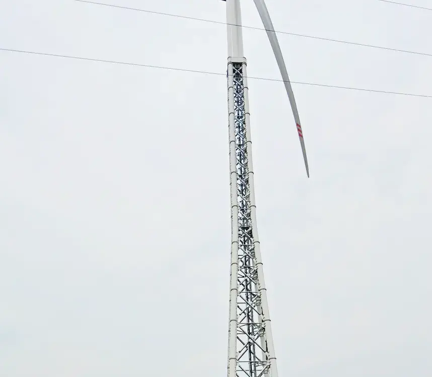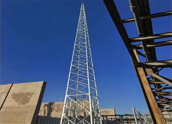
Structural Lightning Protection Towers

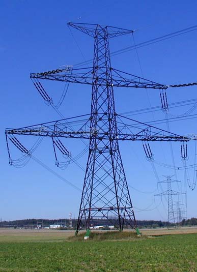
Hot Dip Galvanized Steel Lattice Power Transmission Tower
July 13, 2026
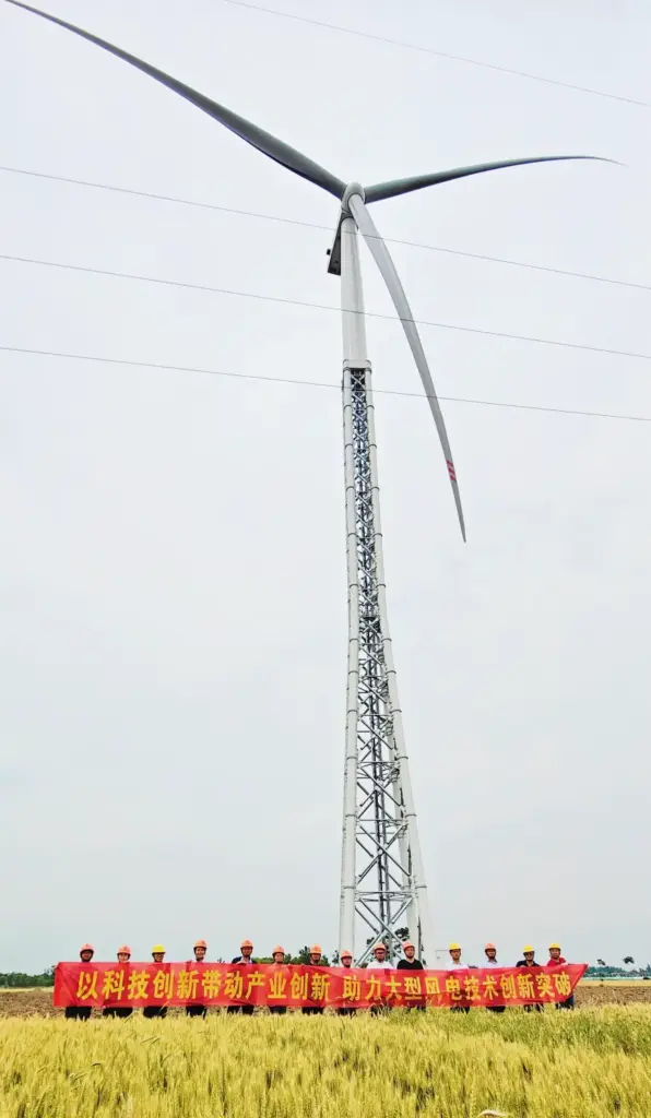
Lattice Steel Structure Tower for Wind
September 7, 2026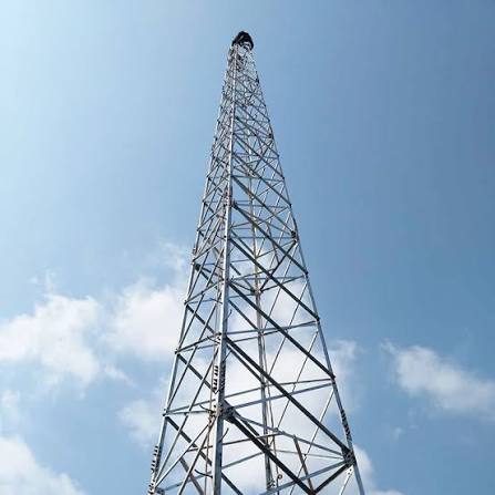
Structural Lightning Protection Towers & Lightning Rod Towers
Comprehensive Engineering Manual, Metallurgical Specifications, Wind Load Dynamics, and Standard Compliance Matrix for Industrial, Petrochemical, Power Grid, and Telecommunication Infrastructure Facilities.
Design Code: GB50057 / CECS 80
Height Span: 10m to 60m
Steel Grades: Q235B / Q355B / SS304
Anti-Corrosion: Hot-Dip Galvanized (ISO 1461)
Section 1.0
Executive System Overview & Material Classifications
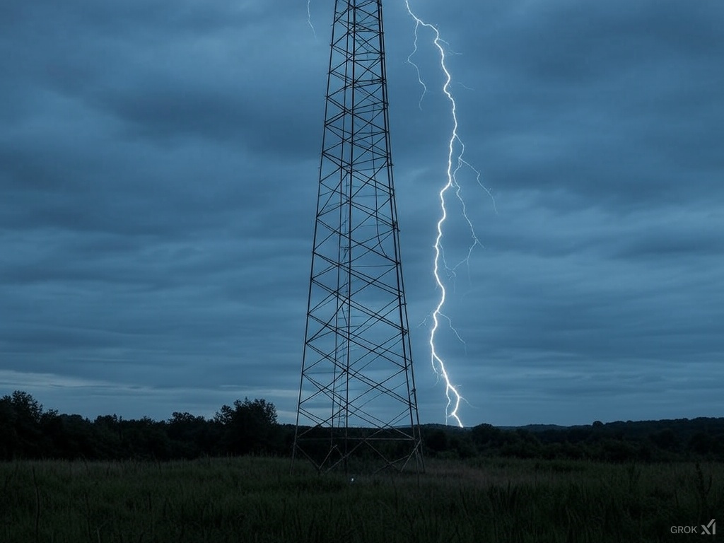
Lightning Protection Towers (also designated as lightning arrestor towers, surge dissipation towers, or lightning shield wire towers) are specialized vertical structural steel assemblies engineered to capture, control, and safely direct high-voltage atmospheric discharge currents (lightning strikes) safely into the earth’s mass. By establishing a preferential strike point, these towers mitigate the risk of direct lightning strikes to hazardous industrial facilities, explosive material storage units, critical power substations, high-frequency communication base stations, and civil infrastructure.
Modern lightning protection structures are broadly segmented by their geometry (triangular lattice, square lattice, or single-pole tubular configurations) and material composition (round bar steel, structural angle steel, structural steel pipe, or architectural stainless steel). Round bar steel and hollow structural steel (HSS) pipe models are extensively specified in high-corrosion or high-wind environments due to their inherently low drag coefficients and superior strength-to-weight ratios.
Lattice Angle Steel Towers
Constructed using hot-rolled equal angle steel (e.g., Q235B/Q355B). Ideal for ultra-tall structures (40m-60m) requiring high torsional rigidity and heavy antenna/equipment mounting payloads alongside lightning receptors.
Tubular Steel & Round Bar Towers
Utilizes seamless or ERW steel pipes for main legs and solid round steel for web bracing. Provides a streamlined aerodynamic profile, reduced overall tower self-weight, and minimized footprint suitable for urban or rooftop integration.
Data Table 1.1
Fundamental Structural & Physical Design Specifications
| Parameter Description | Standard Specification | Engineering Tolerance / Code Requirement | Design Compliance |
|---|---|---|---|
| Standard Height Profile | 10m, 15m, 20m, 25m, 30m, 35m, 40m, 50m, 60m | ± 0.5% of total structure height | GB50057 / CECS 80 |
| Structural Footprint | Triangular Lattice / Square Lattice / Monopole | Base spread 0.8m to 4.5m dependent on height | Optimized Land Saving |
| Primary Structural Material | Q235B, Q355B Structural Carbon Steel / SS304 | Tensile Yield Strength $f_y \ge 235\text{–}355\text{ MPa}$ | GB/T 700 / GB/T 1591 |
| Verticality Deviation | $\le 1 / 1000$ of Total Height | Laser alignment inspection post-erection | CECS 80:2006 |
| Anticorrosion Process | Hot-Dip Galvanizing (HDG) / Duplex Coating | Zinc coating thickness $\ge 86\ \mu\text{m}$ ($610\text{ g/m}^2$) | ISO 1461 / GB/T 13912 |
| Design Operational Life | $\ge 30$ Years (Standard Environment) / $\ge 50$ Years (Heavy HDG) | Zero structural maintenance required within 20 years | Industrial Grade |
Section 2.0
Electro-Geometric Model & Lightning Dissipation Mechanics
The primary functional objective of a lightning protection tower is to attract lightning discharges within a mathematically defined zone and channel the resulting pulse current safely into the grounding electrode system. Modern tower engineering relies on the Rolling Sphere Method (RSM) as codified in national and international standards (GB50057, IEC 62305, IEEE 998).
The protection boundary created by a lightning air terminal of height $h$ is modeled by imaginary spheres with radius $h_r$ (where $h_r$ corresponds to the lightning protection class: Class I $h_r = 30\text{m}$, Class II $h_r = 45\text{m}$, Class III $h_r = 60\text{m}$) rolling over the physical tower structure. The protected radius $R_p$ at a ground clearance plane of height $h_x$ is derived through the precise trigonometric relation:
To eliminate destructive side-flash transitions and secondary induced overvoltages, the tower’s metallic structural assembly acts as a multi-path down-conductor network. The characteristic surge impedance $Z_0$ of the steel tower lattice is engineered to be substantially lower than the down-conductor impedance of standard wires, satisfying $Z_{tower} < \frac{1}{10} Z_{cable}$. This ensures that transient potential rises at the peak ($V_{peak} = L \cdot \frac{di}{dt} + I R_g$) remain well below the breakdown dielectric threshold of neighboring air gaps.
Data Table 2.1
Calculated Protection Radius ($R_p$) vs. Tower Height ($h$) across Protection Classes
| Tower Height ($h$) | Class I Protection ($h_r = 30\text{m}$) | Class II Protection ($h_r = 45\text{m}$) | Class III Protection ($h_r = 60\text{m}$) | Recommended Base Width |
|---|---|---|---|---|
| 15 Meters | 25.98 m | 32.78 m | 38.40 m | 1.20 m – 1.50 m |
| 20 Meters | 28.28 m | 37.41 m | 44.72 m | 1.50 m – 1.80 m |
| 25 Meters | 29.58 m | 41.07 m | 50.24 m | 1.80 m – 2.20 m |
| 30 Meters | 30.00 m (Max) | 44.15 m | 55.07 m | 2.20 m – 2.80 m |
| 40 Meters | N/A (Exceeds $h_r$) | 48.98 m | 63.24 m | 3.00 m – 3.60 m |
| 50 Meters | N/A (Exceeds $h_r$) | N/A (Exceeds $h_r$) | 69.28 m | 3.80 m – 4.50 m |
Section 3.0
Climatic Loading & Operating Environment Parameters
Lightning protection towers are highly exposed tall structures engineered to maintain full elastic structural integrity under combined climatic stresses including extreme wind drag, radial ice accretion, thermal expansion, and seismic ground accelerations.
Wind Pressure ($w_0$)
Calibrated for basic operational survival under wind speeds up to 120–160 km/h (Beaufort Scale 10–12) with minimal sway dynamic deflection.
Seismic Fortification
Designed to withstand peak ground acceleration (PGA) up to $0.20g\text{–}0.30g$ without structural failure or anchor shearing.
Ice Coating Load
Structural calculations incorporate dead-load magnification and increased effective wind frontal area caused by ice accretion.
Foundation Soil Capacity
Compatible with spread concrete footing, pile caps, or rock-anchor foundations across low-bearing to medium-soil conditions.
Data Table 3.1
Geographic & Climatic Deployment Tolerance Matrix
| Deployment Zone | Basic Wind Speed ($v$) | Design Ice Thickness | Ambient Temp Range | Corrosivity Class |
|---|---|---|---|---|
| Coastal / Offshore Marine | 180 – 210 km/h | 0 – 5 mm | -10°C to +50°C | C5 High Marine |
| Inland High Altitude / Alpine | 140 – 160 km/h | 10 – 20 mm | -40°C to +35°C | C2 Low Rural |
| Petrochemical Heavy Industrial | 120 – 150 km/h | 0 – 10 mm | -20°C to +45°C | C4 High Industrial |
| Arid / Desert Regions | 130 – 160 km/h | 0 mm | -15°C to +55°C | C3 Moderate |
Section 4.0
Regulatory Design Codes & Structural Engineering Standards
All steel lightning structures engineered by Jielian Metal Structure Co., Ltd. are strictly calculated, modeled, and manufactured in full compliance with rigorous international and national structural design codes. Structural design calculations utilize second-order $P\text{–}\Delta$ elastic stability analysis to ensure resistance against global dynamic instability and localized element buckling under extreme loading combinations.
Code for Design Protection of Buildings Against Lightning
Code for Design of High-Rise Structures
Standard for Design of Steel Structures
Specification for Construction and Acceptance of Steel Tower-Mast Structures
Data Table 4.1
Normative Engineering Reference Cross-Index
| Technical Scope | Chinese National Standard (GB) | International Equivalence (IEC / ISO) | American Equivalence (ASTM / IEEE) |
|---|---|---|---|
| Lightning Protection Design | GB 50057-2010 | IEC 62305-1/-3 | NFPA 780 / IEEE 998 |
| Structural Carbon Steel | GB/T 700 (Q235B) | ISO 630 S235JR | ASTM A36 |
| High-Strength Structural Steel | GB/T 1591 (Q355B) | ISO 630 S355JR | ASTM A572 Grade 50 |
| Hot-Dip Galvanizing Coating | GB/T 13912-2002 | ISO 1461 | ASTM A123 / A153 |
| Structural Welding Execution | GB 50661-2011 | ISO 5817 Level C | AWS D1.1 Structural Welding |
Section 6.0
Tower Geometries & Structural Configurations
The selection of structural geometry directly dictates total steel consumption, footprint foundation dimensions, erectability in restricted site conditions, and aerodynamic stability. Four major structural typologies are supplied:
1. Triangular Lattice
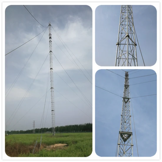
Constructed using 3 main steel pipe legs arranged in an equilateral triangle configuration. Reduces steel weight by 15–20% compared to 4-legged square towers, utilizing external flanged bolt connections subjected purely to axial tensile tension.
2. Square Lattice
Constructed using 4 main angle steel or pipe legs with cross-lacing. Provides high flexural and torsional stability, accommodating heavy auxiliary loads such as microwave dishes, lighting rigs, and multiple down-conductor runs.
3. Monopole Tubular
Single-pole tapered steel tube configuration with polygonal cross-section. Extremely small footprint footprint ($\le 1.2\text{m}^2$) ideal for dense urban substations, gas stations, and space-restricted industrial yards.
4. Decorative Monopole
Features stainless steel architectural cladding, decorative sphere accents, and integrated internal lightning guidance channels. Blends functional lightning safety with urban architectural aesthetics for civic centers and green spaces.
Data Table 6.1
Standard Dimensional & Structural Weight Index (Triangular Steel Pipe Series)
| Tower Model | Nominal Height ($H$) | Top Width ($W_1$) | Base Spread ($W_2$) | Main Leg Pipe Spec | Web Member Spec | Est. Total Weight |
|---|---|---|---|---|---|---|
| GJT-10 | 10 Meters | 400 mm | 1000 mm | $\Phi 60 \times 3.5\text{ mm}$ | $\Phi 25 \times 2.5\text{ mm}$ | ~850 kg |
| GJT-20 | 20 Meters | 500 mm | 1800 mm | $\Phi 76 \times 4.0\text{ mm}$ | $\Phi 32 \times 3.0\text{ mm}$ | ~1,820 kg |
| GJT-30 | 30 Meters | 600 mm | 2600 mm | $\Phi 89 \times 4.5\text{ mm}$ | $\Phi 42 \times 3.0\text{ mm}$ | ~3,450 kg |
| GJT-40 | 40 Meters | 700 mm | 3400 mm | $\Phi 114 \times 5.0\text{ mm}$ | $\Phi 48 \times 3.5\text{ mm}$ | ~5,800 kg |
| GJT-50 | 50 Meters | 800 mm | 4200 mm | $\Phi 140 \times 6.0\text{ mm}$ | $\Phi 60 \times 4.0\text{ mm}$ | ~8,900 kg |
| GJT-60 | 60 Meters | 900 mm | 5000 mm | $\Phi 159 \times 8.0\text{ mm}$ | $\Phi 76 \times 4.5\text{ mm}$ | ~13,200 kg |
Section 7.0
Anti-Corrosion Systems & Surface Treatment Engineering
To achieve a maintenance-free 30-to-50-year service life in aggressive atmospheric environments, all fabricated structural steel assemblies undergo hot-dip galvanizing (HDG) in compliance with ISO 1461 and GB/T 13912 standards.
Prior to galvanizing, steel components undergo acidic pickling, fluxing, and automated immersion into molten zinc baths maintained at $450^\circ\text{C} \pm 5^\circ\text{C}$. This thermal process produces a series of zinc-iron alloy layers metallurgically bonded to the parent steel substrate, providing both physical barrier protection and sacrificial cathodic protection.
Data Table 7.1
Corrosion Protection System & Expected Durability
| Environmental Corrosivity (ISO 12944) | Surface Treatment Specification | Min. Layer Thickness ($\mu\text{m}$) | Est. Service Life to First Major Maintenance |
|---|---|---|---|
| C2 (Low – Rural / Arid) | Standard Hot-Dip Galvanizing | $65\ \mu\text{m}\ (460\text{ g/m}^2)$ | > 50 Years |
| C3 (Medium – Urban / Light Ind.) | Standard Hot-Dip Galvanizing | $86\ \mu\text{m}\ (610\text{ g/m}^2)$ | 30 – 40 Years |
| C4 (High – Industrial / Inland Marine) | Heavy HDG + Passivation | $100\ \mu\text{m}\ (710\text{ g/m}^2)$ | 25 – 30 Years |
| C5 (Very High – Marine / Offshore) | Duplex Coating System (HDG + Epoxy Polyurethane) | $86\ \mu\text{m}\ \text{HDG} + 140\ \mu\text{m}\ \text{Paint}$ | > 35 Years |
Section 8.0
Industrial Applications & Deployment Environments
Lightning Protection Towers are deployed across critical infrastructure assets where secondary spark discharges or unguided atmospheric strikes pose disastrous thermal, explosive, or electrical surge risks.
Petrochemical & Refining
Oil refineries, LNG terminals, bulk gas storage facilities, chemical processing workshops, and fuel distribution depots.
Power Grid & Utilities
High-voltage transmission substations, thermal/hydroelectric power plants, solar PV central inverter stations, and wind farm hubs.
Telecom & Defense
Cellular mobile base stations (5G), radar tracking domes, satellite earth stations, military command posts, and missile sites.
Mining & Heavy Industry
Coal preparation plants, underground mine headframes, explosive storage magazines, paper mills, and steel manufacturing plants.
Transportation Infrastructure
Commercial airport flight control towers, weather radar stations, railway traction substations, and seaport container terminals.
Forestry & Agriculture
Forest fire monitoring watchtowers, grain storage silos, and remote environmental observation stations.
Section 9.0
Erection Engineering & Installation Sequence Protocols
Proper site assembly and erection of a lightning protection tower requires strict structural sequencing to ensure structural stability, vertical alignment tolerances, and electrical earth continuity.
Site Assessment & Civil Foundation Casting
Geotechnical soil testing confirms bearing capacity ($\ge 100\text{ kPa}$). Reinforced concrete footings (Grade C25/C30) are poured with pre-embedded Grade 8.8 J-bolt anchor cages positioned via precision steel templates. Concrete must cure to $\ge 85\%$ design strength prior to steel erection.
Grounding Grid Interconnection
Excavation of a perimeter ring earth electrode grid using $40 \times 4\text{ mm}$ hot-dip galvanized flat steel or $95\text{ mm}^2$ copper conductors buried $\ge 0.8\text{m}$ below grade. Low-resistance earth enhancement compounds or chemical ground electrodes are integrated to achieve $R_g \le 10\ \Omega$ ($R_g \le 1\ \Omega$ for power substations).
Segmented Lattice Assembly & Erection
Modular tower sections are assembled on ground mats or hoisted sequentially using mobile cranes or gin-poles. External structural flanges are mated with Grade 8.8/10.9 hot-dip galvanized high-strength bolts torqued to specified pre-tension values using calibrated torque wrenches.
Air Terminal & Down-Conductor Alignment
The primary stainless steel air terminal rod is mounted securely to the top tower cap plate. Direct mechanical bonding is established between the air terminal, structural steel main legs, and down-conductors, ensuring exothermic welded or bolted connections feature contact resistance $< 0.03\ \Omega$.
Verticality Verification & Final Commissioning
Dual orthogonal theodolite laser measurements confirm total structure verticality deviation is within $\le 1/1000$. Earth ground resistance is measured using the 3-pole fall-of-potential test method under dry soil conditions prior to operational sign-off.
Data Table 9.1
Quality Assurance Maintenance & Inspection Schedule
| Inspection Item | Testing Protocol / Tool | Frequency | Acceptance Threshold | Corrective Action |
|---|---|---|---|---|
| Ground Resistance | 3-Pole Earth Tester | Bi-annually (Pre-Lightning Season) | $R_g \le 10\ \Omega$ (or $\le 1\ \Omega$) | Inject resistance-reducing agent / expand grid |
| Bolt Torque Fastening | Calibrated Torque Wrench | Annually / Post-Storm Event | 100% specified design torque | Re-torque loose bolts; replace damaged washers |
| Galvanized Coating Thickness | Magnetic Coating Thickness Gauge | Every 3 Years | Thickness $\ge 65\ \mu\text{m}$ | Clean rust scale and apply zinc-rich cold galvanizing compound |
| Structure Verticality | Optical Laser Theodolite | Every 5 Years / Post-Seismic | Deviation $\le 1 / 1000$ | Shimming base flanges or tensioning guy wires |
Data Table 10.0
Engineering & Procurement Summary Datasheet
| Spec Parameter | Standard Manufacturing Offerings | Custom Engineering Capability |
|---|---|---|
| Structure Heights | 10m, 15m, 20m, 25m, 30m, 35m, 40m, 50m, 60m | Custom heights up to 100m upon engineering review |
| Primary Steel Grades | Q235B (ASTM A36) / Q355B (ASTM A572 Gr50) | Austenitic Stainless Steel 304 / 316L / Weathering Steel |
| Anti-Corrosion Finish | Hot-Dip Galvanized to ISO 1461 ($\ge 86\ \mu\text{m}$) | Duplex Systems (HDG + Fluorocarbon / Epoxy Polyurethane Paint) |
| Connection Methodology | External Flanged Bolt Joints / Overlapping Sleeve Joints | Full Penetration Field Welded Joints / Internal Hidden Flanges |
| Wind Load Rating | 0.40 – 0.70 kN/m² (120 – 160 km/h) | High-Typhoon Class up to 1.20 kN/m² (250 km/h) |
| Seismic Rating | Fortification Level 8 ($PGA = 0.20g$) | Level 9 Seismic Reinforcement ($PGA = 0.40g$) |
| Aviation Safety Accessories | Optional Mounting Brackets | ICAO Medium Intensity Type A/B Solar Aviation Obstruction Lights |
| Climbing Facilities | Internal / External Step Bolts | Safety Climbing Ladder with Fall Arrest Cable System & Rest Cages |
“`