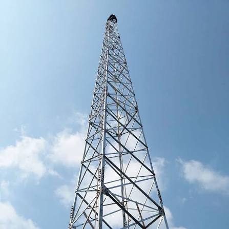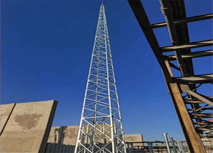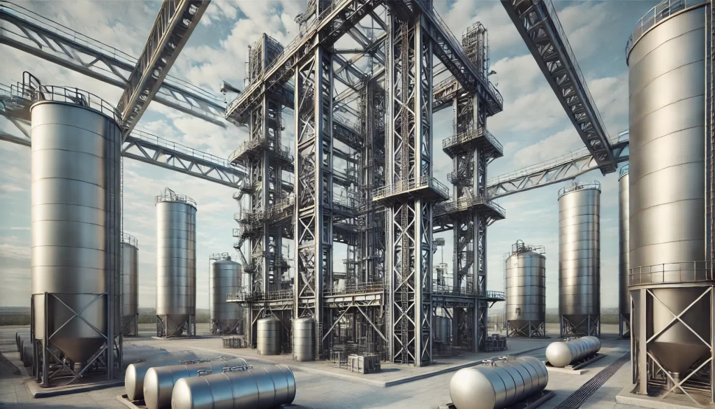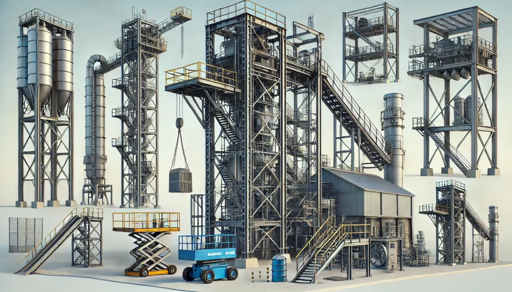
Lattice Steel Structure Tower for Wind

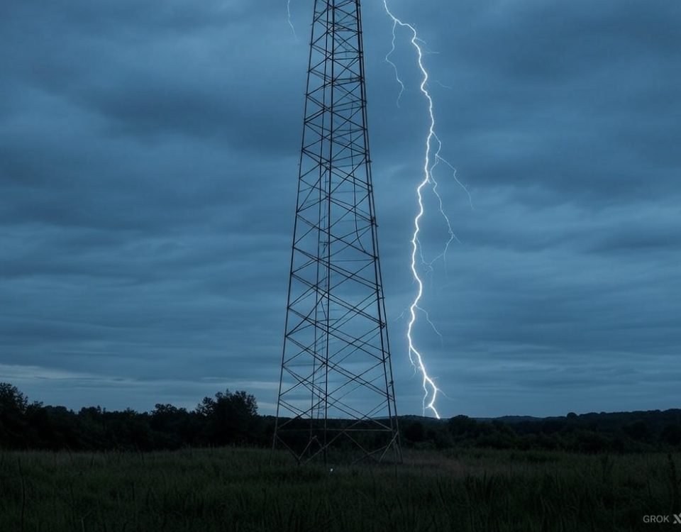
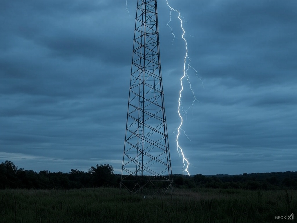
Structural Lightning Protection Towers
August 16, 2026
Corrosion Prevention for Transmission Line Tower Structures
September 26, 2026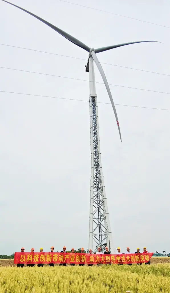
Lattice Steel Structure Tower FOR Wind
Comprehensive Technical Guide to High-Height Lattice Structural Towers, Material Integrity (GB Q355B / ASTM A572 Gr50 / S355JR), Structural Dynamics, Corrosion Protections, and Global Renewable Energy Deployments.
Quality: ISO 9001 Certified
Design Life: 35+ Years
1. Key Metric Benchmarks & Mechanical Overview
2. Comprehensive Structural Engineering Specifications Table
The table below presents the master design baseline parameters governing the structural design, fabrication tolerances, environmental durability, and operational limits of industrial lattice steel towers deployed for wind resource assessment and utility-scale turbine installation.
| Technical Parameter | Engineering Standard & Operational Specification |
|---|---|
| Tower Overall Height | Custom engineered from 10m to 160m (Or tailored to site requirements) |
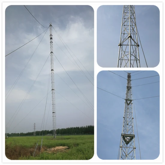
| Structural Configuration Types | Self-Supporting 3-Leg/4-Leg Lattice, Guyed Mast Lattice, Monopole, or Hybrid Truss Structure |
| Primary Structural Steel Grade | Chinese Standard GB Q355B, Q235B / ASTM A36, ASTM A572 Grade 50 / EN BS S355JR, S235JR |
| Basic Design Wind Speed | Up to 60 m/s (3-second gust) or customized based on local meteorological extremes |
| Rest Platforms & Work Stages | Customized quantity (Internal rest platforms, top work deck, intermediate safety stages with handrails) |
| Equipment & Payload Capacity | Anemometers, Wind Vanes, LiDAR/SoDAR units, Aviation Obstruction Lights, Microwave Dishes, Solar Panels |
| International Design Standards | GB 50017 / ANSI / TIA-222-G / TIA-222-H / Eurocode 3 (EN 1993) / ISO 1461 |
| Surface Anti-Corrosion Treatment | Hot-Dip Galvanizing (HDG) per ISO 1461 / ASTM A123, optional epoxy painting or plastic spraying coating |
| Exterior Finish Color Scheme | Standard Natural Zinc Grey, Aviation Red-White Signal Stripes, or Custom RAL Color Powder Coating |
| Seismic Resistance Grade | Designed to withstand Grade 8 Seismic Dynamic Intensities (PGA up to 0.4g) |
| Verticality Manufacturing Tolerance | Strictly ≤ 1 / 1000 of overall tower height |
| Operational Temperature Rating | Extreme Arctic/Desert Performance range from -45°C to +45°C |
| Radial Ice Coating Load Capacity | Engineered to handle 5 mm to 10 mm radial ice accumulation without structural collapse |
| Grounding Resistance System | Integrated lightning mitigation system ensuring overall ground resistance ≤ 4 Ω |
| Fasteners & Structural Bolts Grade | High-tensile Grade 6.8, Grade 8.8, and Grade 10.9 structural bolts (Hot-dip galvanized) |
| Operational Service Design Life | 35+ Years in aggressive corrosive atmospheric and offshore maritime environments |
| Quality Certification Baseline | ISO 9001:2015, ISO 14001, ISO 45001, CE Certification, EN 1090-1 / EXC3 |
3. Structural Components Architecture & Anatomy
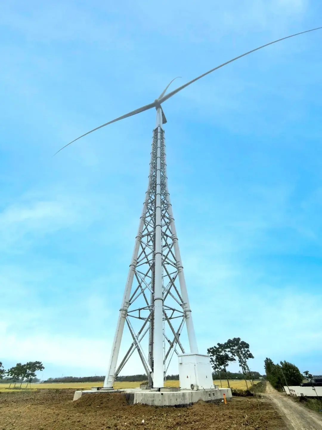
A commercial wind measurement or structural lattice tower comprises an array of interconnected precision-engineered components designed to transfer dynamic aerodynamic loads safely to the foundation structure. Each module serves a specific mechanical purpose:
Main Leg Columns & Base Anchor Assembly
The tower base and main leg columns constitute the primary axial load-bearing frame. Manufactured from high-yield structural steel angle profiles or hollow tubular sections, these members withstand heavy compression and uplift tension forces. The base anchor assembly features heavy-duty anchor bolt cages embedded deeply in reinforced concrete foundations.
Crossbars, Diagonal Bracing & Web Members
Lattice structures rely on horizontal crossbars and diagonal bracing lattices (K-bracing, X-bracing, or Warren truss patterns) to resist lateral shear forces, torsional moments, and wind-induced vortex shedding. These structural elements prevent localized buckling of the primary leg members under severe environmental loads.
Anemometer Brackets & Sensor Mounts
To secure pristine meteorological data without flow distortion caused by the tower structure, specialized extension booms and anemometer brackets are integrated at multiple vertical heights. These rigid cantilever arms ensure precise positioning of wind vanes, ultrasonic anemometers, and temperature/pressure sensor housings.
Lightning Rods, Guy Wires & Safety Accessories
A terminal air-rod (lightning rod) mounted atop the structure redirects atmospheric electrical discharges safely through copper down-conductors into the ground grid. For guyed lattice variants, high-tensile galvanized steel guy wires with turnbuckles and torque bars provide essential lateral stability under reduced foundation footprints.
4. Material Chemical Composition Specifications (% max)
The mechanical integrity and weldability of lattice towers depend on strict control of structural steel chemistry. Below is the maximum threshold elemental analysis breakdown across international grade equivalents used in our manufacturing process.
| Steel Grade Standard | Carbon (C) | Silicon (Si) | Manganese (Mn) | Phosphorus (P) | Sulfur (S) | Vanadium (V) | Niobium (Nb) | Titanium (Ti) |
|---|---|---|---|---|---|---|---|---|
| GB Q355B | ≤ 0.20 | ≤ 0.50 | ≤ 1.60 | ≤ 0.035 | ≤ 0.035 | ≤ 0.15 | ≤ 0.07 | ≤ 0.20 |
| ASTM A572 Gr50 | ≤ 0.23 | ≤ 0.40 | ≤ 1.35 | ≤ 0.040 | ≤ 0.050 | ≤ 0.15 | ≤ 0.05 | ≤ 0.05 |
| EN S355JR | ≤ 0.24 | ≤ 0.55 | ≤ 1.60 | ≤ 0.035 | ≤ 0.035 | – | – | – |
| GB Q235B | ≤ 0.20 | ≤ 0.35 | ≤ 1.40 | ≤ 0.045 | ≤ 0.045 | – | – | – |
| ASTM A36 | ≤ 0.26 | ≤ 0.40 | – | ≤ 0.040 | ≤ 0.050 | – | – | – |
5. Structural Steel Mechanical Properties & Testing Data
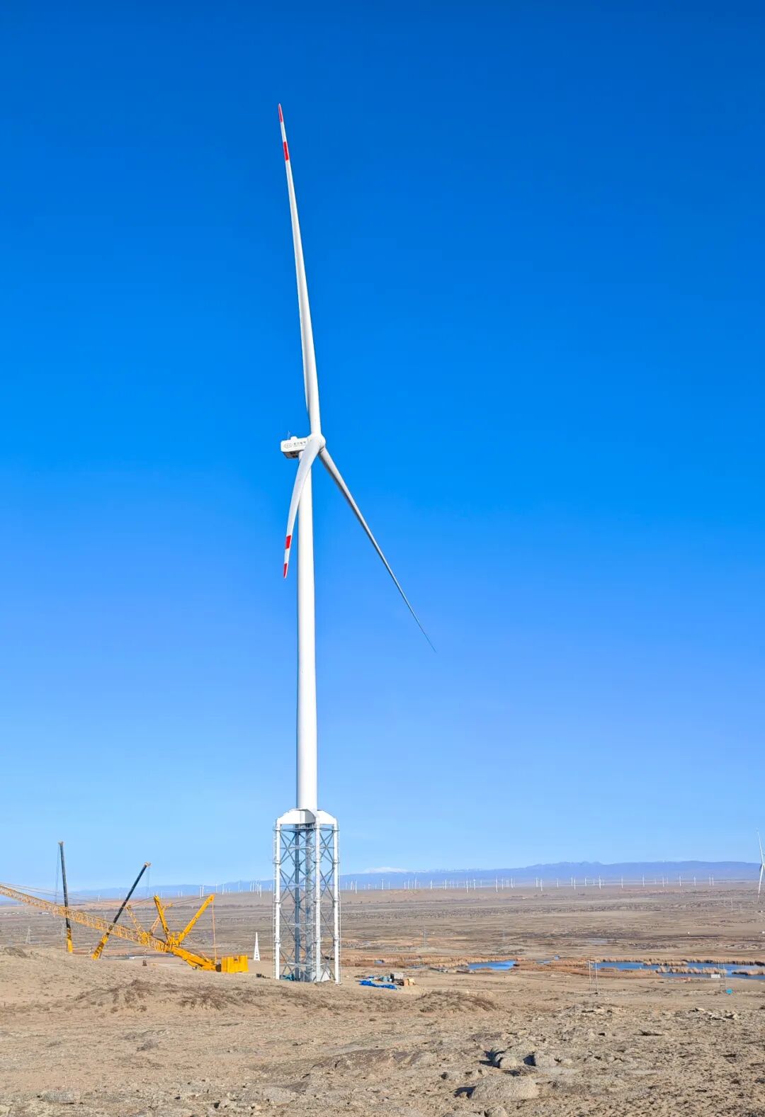
To guarantee fatigue life and structural stability across extreme temperature ranges (-45°C to +45°C), all raw steel structural members undergo rigorous tensile testing, Charpy V-notch impact tests, and yield strength verification prior to fabrication.
| Steel Grade | Yield Strength ReH (MPa) | Tensile Strength Rm (MPa) | Elongation A5 (%) | Charpy V-Notch Impact (J) | Test Temperature (°C) |
|---|---|---|---|---|---|
| GB Q355B | ≥ 355 | 470 – 630 | ≥ 20 | ≥ 34 J | 20°C / 0°C / -20°C |
| ASTM A572 Gr50 | ≥ 345 (50 ksi) | ≥ 450 (65 ksi) | ≥ 18 | ≥ 27 J | -20°C |
| EN S355JR | ≥ 355 | 470 – 630 | ≥ 22 | ≥ 27 J | 20°C |
| GB Q235B | ≥ 235 | 370 – 500 | ≥ 26 | ≥ 27 J | 20°C |
| ASTM A36 | ≥ 250 (36 ksi) | 400 – 550 | ≥ 20 | ≥ 27 J | 20°C |
Key Features of Meteorological & Wind Assessment Lattice Towers
- Uninterrupted 24/7 Wind Condition Observation: Continuous monitoring of wind speed profiles, shear exponents, turbulence intensity, wind direction vectors, and air density across multiple elevation zones.
- Automated Data Acquisition & Logging: Direct connectivity with high-precision data loggers, satellite telemetry, cellular remote monitoring systems, and solar power packs.
- Rapid Deployment & Low Maintenance: Modular standardized lattice framing enables rapid on-site assembly with minimal crane intervention; standard measurement logging cycles run at 5-minute to 10-minute intervals.
- Aerodynamic Minimal Drag Index: Open lattice truss geometry significantly reduces wind blockage factors, providing uncorrupted wind flow readings at all anemometer levels.
6. Wind Turbine Tower Structural Comparison Matrix
Selecting the appropriate tower architecture requires evaluating manufacturing costs, logistics constraints, foundation requirements, and hub heights. Below is a engineering comparison of the three primary commercial wind turbine support structures:
| Structural Parameter | Lattice Steel Structure Tower | Flexible Tubular Steel Tower | Hybrid Concrete-Steel Tower |
|---|---|---|---|
| Primary Material Construct | High-strength bolted steel angles / structural tubes | Rolled steel plate welded cylindrical/conical shell | Pre-cast concrete lower segments + steel upper tube |
| Optimal Target Hub Height | 100m to 170m+ (Extremely cost-effective for high heights) | 80m to 120m (Constrained by shell diameter transport) | 140m to 180m+ (Ultra-tall onshore turbine applications) |
| Transportation Logistics | Flat-pack containerized transport; negligible highway limit impact | Requires oversize heavy-haul transport; limited by bridge clearances | Modular pre-cast concrete segments transported via standard trucks |
| Foundation Footprint & Concrete Volume | 4-leg spread foundation with concrete-filled steel tubes (CFST); reduced concrete volume | Large heavy gravity base or deep pile cap foundation required | Extremely heavy deep foundation block required for deadweight stability |
| On-Site Installation Effort | Bolted assembly on site; light crane lifting requirements | Heavy mobile crane lifting for thick shell segment stacking | Complex slip-form casting or segment tensioning + heavy crane placement |
| Capital Expenditure (CAPEX) Efficiency | Highest steel mass saving (up to 40% steel mass reduction vs tubular) | Moderate to High; sensitive to global steel plate pricing | High initial CAPEX; economical only for extreme hub height projects |
7. Global Renewable Energy Application Scenarios
Engineered specifically to survive extreme marine atmospheric conditions and harsh hydrodynamic forces in offshore wind farms across Europe, North America, and Asia-Pacific.
| Corrosion Class | C5-M / CX Extreme Marine Atmosphere |
| Wave & Load Resistance | Designed for combined hydrodynamic wave loads & cyclic wind fatigue |
| Coating System | Duplex System (HDG + Multi-layer Marine Epoxy Painting) |
| Target Deployment | Nearshore sub-stations, offshore meteorological towers, jacket turbine tops |
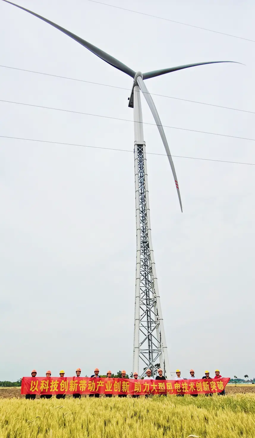
Optimized for onshore installation environments including mountain ridges, desert terrain, high-altitude plateaus, and forested plains where logistics severely restrict heavy transport.
| Terrain Adaptability | Plains, steep mountain ridges, remote deserts, cold arctic regions |
| Logistics Flexibility | Modular component sizes fit standard 40ft container transport |
| Environmental Adaptability | Resistant to high UV, sandstorm abrasion, and low-temperature brittle fracture |
| Target Deployment | Utility-scale land wind farms, remote microgrids, site feasibility assessment |
8. Precision Manufacturing & Quality Control Workflow
Our automated steel tower manufacturing plant utilizes state-of-the-art CNC machining centers, automated submerged arc welding (SAW), and environmental hot-dip galvanizing lines to maintain strict dimensional accuracy and structural integrity.
Steel angle plates and tubular profiles undergo high-speed CNC thermal cutting, drilling, and high-precision hydraulic stamping to achieve sub-millimeter hole alignment.
Gusset plates, node joints, and mounting flanges are assembled on precision structural jigs to ensure 100% geometric accuracy before welding.
Certified welders execute SMAW/FCAW/SAW welds followed by 100% Non-Destructive Testing (NDT) including Ultrasonic (UT) and Magnetic Particle Inspection (MPI).
Components undergo acid pickling and immersion in a molten zinc bath at 450°C (ISO 1461), followed by trial shop assembly to guarantee zero-defect field erection.
9. Standard Equal Angle Structural Steel Dimensional Weight Reference Table
Lattice steel towers utilize hot-rolled equal angle steel profiles (GB/T 706, ASTM A6, EN 10056) for primary leg members and web bracing systems. Below are standard engineering properties used in structural modeling:
| Designation (Leg x Thickness mm) | Cross-Sectional Area (cm²) | Nominal Weight (kg/m) | Center of Gravity Cx (cm) | Moment of Inertia Ix (cm⁴) | Radius of Gyration ix (cm) |
|---|---|---|---|---|---|
| L 75 x 75 x 6 | 8.73 | 6.85 | 2.06 | 46.2 | 2.30 |
| L 90 x 90 x 8 | 13.90 | 10.90 | 2.51 | 104.0 | 2.74 |
| L 100 x 100 x 10 | 19.20 | 15.10 | 2.82 | 178.0 | 3.04 |
| L 125 x 125 x 10 | 24.20 | 19.10 | 3.44 | 357.0 | 3.84 |
| L 140 x 140 x 12 | 32.40 | 25.50 | 3.86 | 598.0 | 4.29 |
| L 160 x 160 x 14 | 43.30 | 34.00 | 4.41 | 1050.0 | 4.92 |
| L 180 x 180 x 16 | 55.40 | 43.50 | 4.95 | 1720.0 | 5.57 |
| L 200 x 200 x 20 | 76.40 | 60.00 | 5.52 | 2870.0 | 6.13 |
10. Anti-Corrosion Coating & Hot-Dip Galvanizing Thickness Table
Corrosion durability is a key design factor for achieving a 35+ year service lifespan. Galvanization thickness complies strictly with ISO 1461, ASTM A123, and GB/T 13912 requirements based on structural steel thickness:
| Steel Material Thickness (t) | Local Coating Thickness (Min μm) | Average Coating Thickness (Min μm) | Local Coating Density (g/m²) | Estimated Durability (C3 Atmosphere) |
|---|---|---|---|---|
| t < 1.5 mm | 45 μm | 55 μm | 390 g/m² | 25 Years |
| 1.5 mm ≤ t < 3.0 mm | 55 μm | 70 μm | 500 g/m² | 35 Years |
| 3.0 mm ≤ t < 6.0 mm | 70 μm | 85 μm | 610 g/m² | 45+ Years |
| t ≥ 6.0 mm | 79 μm | 86 μm – 100 μm | 705 g/m² | 50+ Years |
11. Structural Fasteners & Structural Bolt Technical Specifications
Lattice tower joints rely on high-tensile structural bolting assemblies conforming to ISO 898-1, ASTM A325, or ASTM A490 to prevent slip under cyclic aerodynamic vibrations.
| Bolt Mechanical Grade | Nominal Yield Strength (MPa) | Tensile Strength (MPa) | Proof Load Stress (MPa) | Primary Application Joint Type |
|---|---|---|---|---|
| Grade 6.8 Structural Bolt | 480 MPa | 600 MPa | 440 MPa | Secondary bracing, ladder mounts, platforms |
| Grade 8.8 High Tensile Bolt | 640 MPa | 800 MPa | 600 MPa | Primary leg joint connections, diagonal trusses |
| Grade 10.9 Structural Bolt | 900 MPa | 1000 MPa | 830 MPa | Heavy load tower base connection flanges |
12. Environmental Hazard Mitigation & Load Analysis
Wind lattice steel structures operate under severe climatic threats. Structural design calculations incorporate dynamic response spectrum analyses to resist environmental extremes:
Seismic Dynamic Response
Complies with Grade 8 seismic intensity standards. Flexible lattice framing offers superior energy dissipation compared to rigid solid structures under earthquake conditions.
Ice Accretion Tolerances
Calculated for 5mm to 10mm radial ice accumulation combined with extreme wind velocity loading without localized member buckling.
Thermal Variation Ranges
Designed for extreme thermal expansion/contraction cycles from arctic frost (-45°C) to intense desert heat (+45°C).
13. Foundation Engineering Options & Soil Adaptability
The foundation system transfers extreme overturning moments and shear forces into the ground safely. Choosing the optimal foundation type depends directly on site geotechnical soil investigations:
| Foundation Type | Geotechnical Soil Condition | Reinforced Concrete Volume | Primary Advantage |
|---|---|---|---|
| 4-Pad Spread Concrete Slab Foundation | Standard dense soil, gravel, consolidated clay | Moderate (Distributed across 4 corner pads) | Economical excavation, fast pouring execution |
| Micro-Pile / Drilled Shaft Foundation | Hard bedrock or steep mountainous rocky slopes | Low (High steel anchor pin density) | Minimal terrain disturbance, ideal for mountain ridges |
| Concrete-Filled Steel Tube (CFST) Base | Soft soil, coastal mudflats, high water table zones | Moderate-High | Extreme load capacity, enhanced lateral stiffness |
| Guy Wire Anchor Block System | Expansive flat terrain, agricultural land | Very Low (Central base pad + 3/4 guy anchors) | Lowest capital cost for ultra-tall measurement masts |
14. Quality Control & Quality Assurance Protocol
Every structural batch undergoes comprehensive QA/QC testing strictly before factory dispatch. Our quality control procedure covers three primary inspection phases:
1. Incoming Material Testing
Mill Test Certificates (MTC EN 10204 3.1) accompanying all raw steel plates and angle channels. Physical chemical verification performed via spectrographic analysis.
2. In-Process NDT Inspection
Visual Inspection (VT 100%), Ultrasonic Testing (UT 20-100% on structural welds), and Magnetic Particle Inspection (MPI) to detect surface or internal discontinuities.
3. Post-Galvanizing QA Checks
Magnetic gauge coating thickness checks across all structural members, adhesion grid testing, and pre-shipping assembly alignment checks.
15. Global Standards & Structural Code Compliance Matrix
Our engineering department utilizes PLS-TOWER, ANSYS, and SAP2000 structural analysis software certified to meet global building codes:
| Region / Authority | Structural Design Code | Steel Fabrication Standard | Galvanizing / Coating Code |
|---|---|---|---|
| North America (USA/Canada) | ANSI / TIA-222-G / TIA-222-H / ASCE 7 | AISC 360 / AWS D1.1 Welding Code | ASTM A123 / ASTM A153 |
| European Union (EU) | Eurocode 3 (EN 1993-1-1 / EN 1993-3-1) | EN 1090-1 / EN 1090-2 EXC3 (CE Marked) | EN ISO 1461 |
| China (GB National) | GB 50017 / GB 50009 / GB 50135 | GB/T 13912 / GB 50205 | GB/T 13912 |
| International / ISO Baseline | ISO 2394 General Principles on Reliability | ISO 3834 Welding Quality Requirements | ISO 12944 Paint System Corrosion Class |
16. On-Site Erection, Safety Maintenance & Lifecycle Management
Modular lattice steel structure towers are optimized for effortless site logistics and safe vertical assembly. The following operational lifecycle parameters ensure long-term structural safety:
A. Modular Field Erection
Lattice sections are pre-assembled on ground level into 6m-9m sub-assemblies before vertical lifting. Flanged joints and step-leg ladders ensure safe technician climbing during installation.
B. Maintenance Routines
Scheduled annual maintenance checks focus on torque checking primary joint bolts, inspecting guy wire tensions (if applicable), and verifying grounding rod earth resistance (≤4Ω).
C. Decommissioning & Recycling
At end-of-life (35+ years), 100% of the structural steel members are fully recyclable, aligned with global circular economy goals and environmental sustainability standards.
17. Frequently Asked Engineering Questions (Technical FAQ)
Q1: What is the primary advantage of a lattice wind tower over a tubular tower?
A: Lattice wind towers provide a dramatic reduction in overall steel weight (up to 40% saving), lower total transportation costs, and a significantly smaller foundation concrete requirement. Because components can be flat-packed into standard shipping containers, lattice towers can easily be deployed to remote, mountainous, or difficult-to-access sites where heavy tubular shell transport is logistically impossible.
Q2: How does hot-dip galvanizing ensure a 35+ year service life in offshore or coastal areas?
A: Hot-dip galvanizing per ISO 1461 / ASTM A123 forms a series of zinc-iron alloy layers metallurgically bonded to the underlying steel. Under atmospheric exposure, zinc forms a protective zinc carbonate patina. For high-corrosion offshore environments (C5-M class), a duplex coating system (galvanizing plus epoxy/polyurethane topcoats) is applied to achieve multi-decade corrosion resistance without requiring structural maintenance.
Q3: What engineering controls ensure strict verticality (1/1000 tolerance)?
A: Verticality tolerance is achieved through precision CNC thermal cutting and hole drilling, jig-verified shop pre-assembly, and calibrated double-nut base plate anchor assemblies. During field installation, total station optical surveying instruments monitor alignment continuously as each vertical leg tier is tightened to design torque specifications.
Q4: Can the lattice steel structure accommodate multi-brand anemometry and LiDAR devices?
A: Yes. All lattice towers feature modular extension booms and standardized universal instrument brackets compatible with major meteorological sensors (NRG Systems, Thies Clima, Vector Instruments) and ground/top-mounted LiDAR/SoDAR wind profiling hardware.
Request Custom Wind Lattice Tower Engineering & Quotation
Partner with experienced structural steel tower manufacturers. We offer turnkey structural calculation, custom CAD drafting, CNC manufacturing, and global project shipping.