
Dealing with Overweight 5G steel tower
Steel Tower Design : A Field Engineer’s Guide to Selection and Design
February 17, 2026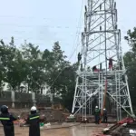
Communication Tower Installation Quality Standards Guide
February 23, 2026Dealing with Overweight 5G AAUs: How We “Patch” the Tower – A Hardcore Reinforcement Case Study
You’ve hit the sore spot. These 5G AAUs? Let me tell you, they are a structural engineer’s nightmare. Those RF planning guys, they’ll pat their chests in meetings and say, “It’s just one more box, not heavy at all!” Then we run the numbers, and holy smokes, just one of those AAUs, with its mounting bracket, has a wind load projected area 40% larger than the old separate units, and the weight has doubled.
The original design was from 10 years ago. Back then, the top had three slender 2G antennas, light as a clothesline. Now they want to hang three AAUs, each with a bulky RRU, or integrated ones. That top section of the tower, the stress ratio (Unity Check) shot from 0.6 to 1.4. Red. Failing. A complete mess.
What do you do? Tear the tower down and rebuild? The client would have your head. The only option is reinforcement. It’s like when a person’s bones aren’t strong enough, you put on splints, add steel pins. We call this kind of job “orthopedic surgery.”
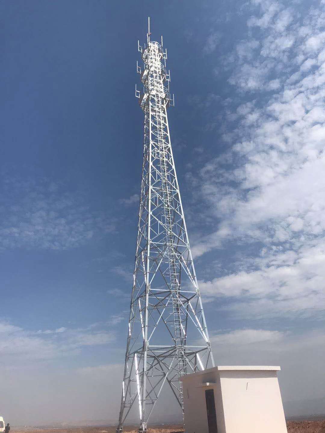
That particular tower was a 60-meter, three-tube lattice tower. The top 5 meters, which we call the “top section” or “lightning rod section,” was the problem. The steel tubes there were smaller and thinner-walled, originally designed for lightweight whip antennas. Now it had to hold three large panels. When the wind blows, all that bending moment gets concentrated right at the base of that top section, on the flange ring and connecting bolts.
We came up with two solutions and ended up using a combination of both. Let me break it down for you:
Solution 1: Tower Body Hoops + Vertical Channel Stiffeners – “Armor for the Skinny Guy”
This was the primary load-bearing reinforcement. We couldn’t cut and replace the main leg members, which would mean rebuilding. Our goal was load sharing.
1. The Core Logic:
Assume the original leg member was a steel tube, say φ168×6. Its section modulus wasn’t enough. So, we welded two channels, back-to-back, along the vertical axis tightly against the existing tube. For instance, [12 channels – that is, C12 channels, 120mm high. These two channels, combined with the original round tube through intermittent welding, form a composite section.
This is all about calculating the moment of inertia of the composite section. The original tube’s inertia is I_steel. Adding the two channels, the new composite section’s neutral axis shifts slightly, but the total inertia I_combo increases significantly. The increase depends on the channel size and the reliability of the connection to the original member.
(In the formula, d is the distance from the channel’s centroid to the overall neutral axis of the composite section. This calculation is tedious; we usually model the section directly in FEA software. But for a quick estimate, this formula shows the effect mainly comes from the d² term – the further you place the material from the center, the better.)
The channels act as “stiffeners,” effectively turning a “thin arm” into a “thick arm,” and with flanges, greatly increasing bending capacity.
2. How to Fix Them? – Hoops Are Key!
Just welding the vertical channels on isn’t enough. The force comes from the antennas, through the platform, to the leg. If the channels are only welded to the leg, local deformation of the leg could tear the welds. You must, at intervals, use hoops to tightly bind them together, like a steel band holding a bundle of sticks together.
On the lower part of the top section, where the bending moment was highest, we placed hoops every 1.5 meters. These hoops were made from – you guessed it – channels, but bent into an arc. We took [10 channels and bent them on a specialized hydraulic press to match the triangular cross-section of the tower. These curved sections were then placed around the three main legs, enclosing both the original legs and the new vertical channels.
These hoops were continuously welded. After welding, the three original legs, plus the new vertical channels, were all integrated by these hoops into a highly rigid space truss-frame hybrid structure. The force travels from the leg to the hoop, and the hoop redistributes it to the adjacent channel stiffeners. Everyone shares the load.
Solution 2: Flange and Joint Area Reinforcement – “Casting a Cast on the Joint”
The tower body is fixed, but the force eventually needs to transfer to the section below. Connecting the top and bottom sections is a massive flange ring and dozens of high-strength bolts. We had to check this area.
-
Flange Stiffening: The original flange at the base of the top section was a thick steel ring. Under significant bending moment, the flange itself could deform, or “warp.” We welded triangular stiffener plates underneath the flange (on the inside), just above the connection point to the lower section. These ribs were welded on one side to the underside of the flange and on the other side to the tower leg and the new vertical channels. This dramatically increased the flange’s rigidity, preventing it from being bent like the rim of a pan.
-
Bolt Group Verification: This was the core check. The bending moment M acting on the flange translates into tensile forces on the bolts. Bolts on one side are in tension, bolts on the other side are in compression (the compression is transferred directly through the flange contact). The formula we use:
This calculates the maximum tensile force T_max on the outermost bolt. y_max is the distance from the outermost bolt to the neutral axis, and y_i is the distance of each bolt to the neutral axis. If this force exceeds the allowable capacity of the bolt (e.g., for a Grade 8.8 M24 bolt, the tensile capacity is roughly 0.8 * f_yb * A_e, maybe around 180kN), then you need to either upgrade to high-strength bolts or increase the number of bolts.
For that project, our calculations showed the original M24 bolts were marginal, with no margin left. We recommended the client, since we were already doing hot work, replace all connecting bolts with Grade 10.9 M27 bolts. The torque values had to be recalibrated, jumping from the original ~800 N·m to well over 1100 N·m. The sound of the torque gun on those bolts was different – a deep, solid thud that felt reassuring.
Pits and Solutions During Construction
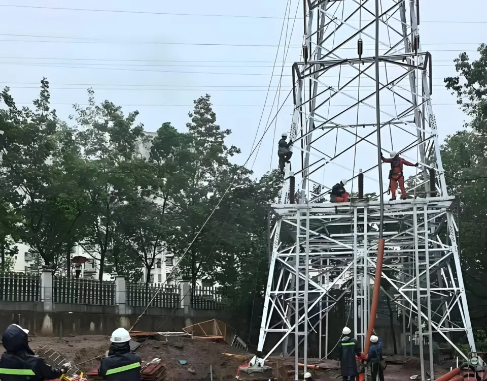
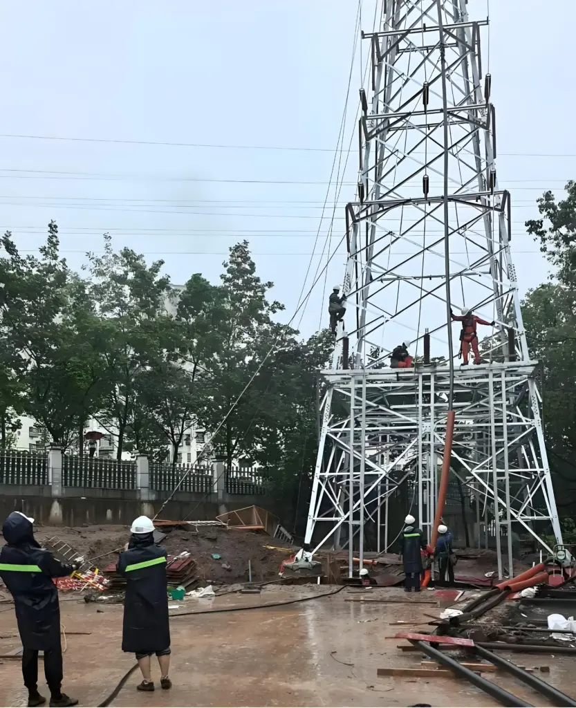
The plan was set, but how do you do the work? High-altitude work, welding, extremely high risk.
-
Temporary Unloading: You cannot weld while the antennas are on. The tower sways; a cooling weld will crack from the stress. We planned this in two steps. First, apply for a nighttime power shutdown and antenna removal. Use a crane to bring those precious AAUs and RRUs down to the ground. Leave just the bare pole on top. This is called “unloading.”
-
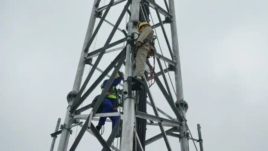
Positioning and Welding: Tower empty, no sway. Our crew goes up. Tack weld the vertical channels in place, then weld from bottom to top. Welders must be certified, specifically for high-altitude work. Use low-hydrogen electrodes, like E5015, baked dry beforehand and kept in portable ovens. Welds must be full, with no undercut, porosity, or slag inclusion. The supervisor (me) climbs up and checks every one with a weld gauge.
-
Hoop Closure: The hardest part was the final joint of each hoop. Three legs, three faces; the hoop is a complete ring. How do you install it? It has to be segmented. We cut each hoop into three segments, welding connecting plates onto each end. On-site, we first tack-welded these three segments onto the legs and stiffeners. Then, we tightened the connection plates with high-strength bolts. Finally, we welded the gap between the connection plates and the hoop segments shut. This ensured the clamping force of the hoop while solving the installation problem.
-
Re-hanging and Acceptance: Reinforcement done, touch up the paint, let it cure. Then re-hang the antennas exactly as before, plus any new ones planned. Finally, use a total station to measure the tower’s verticality and its sway amplitude in light wind. Input the data into the model for comparison. Only when it matches is the job accepted.
A Final Honest Word: This kind of reinforcement isn’t a magic cure-all. It only solves local strength deficiencies. If the entire tower foundation is tilting, nothing you do up top matters. But in this case, using channels and hoops, we turned a condemned tower top into a “tough guy” capable of handling heavy 5G loads. The client saved millions on a tower replacement, and we earned our reputation. This is how we field engineers survive – figuring things out amidst the rubble, using steel and welding rods to give the communication network a second life.