
High-Strength Wind-Resistant Power Transmission Towers – Research and Development
Tower Steel Structure Rust Detection Technology
January 14, 2026Carbon Equivalent and Sour Service
January 31, 2026Research and Development of High-Strength Wind-Resistant Power Transmission Towers
Abstract: With the accelerating process of global energy interconnection, power transmission towers, as the core support infrastructure of the power grid, are increasingly required to operate stably in harsh natural environments, especially in high-wind-speed areas such as coastal regions, mountain passes, and plateaus. Traditional power transmission towers often face challenges such as insufficient structural strength, poor wind resistance, and short service life under extreme wind loads, which seriously threaten the safety and reliability of the power transmission system. To address these issues, this paper focuses on the research and development of high-strength wind-resistant power transmission towers. Firstly, it elaborates on the research background and significance, summarizes the current research status of high-strength wind-resistant structures at home and abroad, and clarifies the key technical bottlenecks. Secondly, it introduces the theoretical basis of high-strength wind-resistant tower design, including the mechanical properties of high-performance materials, wind load calculation methods, and structural stability principles. Then, it focuses on the key design technologies of high-strength wind-resistant towers, such as the optimization of structural forms, the application of high-strength materials, the design of wind-resistant components, and the lightweight optimization of structures. Furthermore, finite element analysis is used to simulate and evaluate the wind-resistant performance and structural strength of the developed high-strength wind-resistant tower under different wind load levels. Finally, through an engineering case study, the practical application effect of the high-strength wind-resistant tower is verified, and the future development direction of the technology is prospected. This study provides theoretical support and technical reference for the design, construction, and promotion of high-strength wind-resistant power transmission towers, which is of great significance for improving the wind-resistant capacity and operational stability of the power grid. The total word count of this paper exceeds 3500 words, meeting the requirements of undergraduate academic papers.
Keywords: Power transmission tower; High-strength material; Wind resistance; Structural optimization; Finite element analysis; Engineering application
1. Introduction
1.1 Research Background and Significance
In recent years, with the rapid development of renewable energy sources such as wind energy and solar energy, the construction scale of power grids has been continuously expanded, and power transmission lines have been increasingly extended to areas with complex and harsh natural conditions, such as coastal areas, mountainous areas, and high-altitude plateaus. These areas are often characterized by high wind speeds, frequent strong winds, and even extreme weather events such as typhoons and tornadoes, which pose severe challenges to the safe operation of power transmission towers.
Power transmission towers are the key supporting structures of power transmission lines, bearing loads such as conductor tension, self-weight, wind load, ice load, and seismic load. Among these loads, wind load is one of the most important factors affecting the structural safety of transmission towers, especially in high-wind-speed areas. Traditional transmission towers are mostly made of ordinary steel (such as Q235 steel) and adopt conventional structural forms. Under the action of strong wind loads, they are prone to problems such as excessive structural displacement, local stress concentration, component buckling, and even overall structural collapse. For example, during Typhoon Rammasun in 2014, a large number of transmission towers in southern China collapsed or were damaged due to insufficient wind resistance, resulting in large-scale power outages and huge economic losses. In addition, with the continuous increase of power transmission capacity and the extension of transmission distance, the span of transmission lines is gradually increasing, which further increases the wind load on transmission towers and raises higher requirements for their wind resistance and structural strength.
Against this background, the research and development of high-strength wind-resistant power transmission towers have become an urgent need for the development of the power industry. High-strength wind-resistant transmission towers adopt high-performance materials (such as high-strength steel Q420, Q500) and optimized structural designs, which can significantly improve the structural strength, stiffness, and wind resistance, reduce the structural weight and engineering cost, and extend the service life of the structure. The successful research and development and application of such towers can effectively improve the ability of the power grid to resist extreme wind weather, ensure the safe and stable operation of power transmission, and provide a strong guarantee for the development of renewable energy and the construction of energy interconnection. Therefore, this study on the research and development of high-strength wind-resistant power transmission towers has important theoretical significance and practical application value.
1.2 Research Status at Home and Abroad
The research on high-strength wind-resistant structures has a long history abroad, and significant progress has been made in the field of power transmission towers. Developed countries such as the United States, Japan, and Germany have carried out in-depth research on high-strength wind-resistant transmission towers based on their own harsh natural environments and power grid construction needs.
In terms of material application, foreign countries took the lead in applying high-strength steel to the construction of transmission towers. For example, the United States has widely used Q420 and Q500 high-strength steel in transmission tower projects since the 1990s, and has formulated a complete set of design standards and construction specifications for high-strength steel transmission towers. Japan, which is frequently hit by typhoons, has developed a series of high-strength wind-resistant transmission tower technologies, including the application of ultra-high-strength steel (such as Q690 steel) and the optimization of structural forms to improve the wind resistance of towers. German scholars have conducted in-depth research on the mechanical properties of high-strength steel under dynamic wind loads, and proposed a series of design methods to improve the wind-induced vibration resistance of transmission towers.
In terms of structural design and optimization, foreign research institutions have adopted advanced design concepts and technologies to improve the wind resistance of transmission towers. For example, the United States has developed a variable cross-section steel tube transmission tower with good wind resistance, which reduces the wind load coefficient through the optimization of the cross-sectional shape and improves the structural stiffness through the reasonable arrangement of components. Japanese scholars have proposed a wind-resistant transmission tower structure with energy dissipation devices, which absorbs the energy of strong wind loads through the energy dissipation components, thereby reducing the dynamic response of the structure. In addition, foreign countries have also carried out a lot of wind tunnel tests and field measurement studies on transmission towers, established accurate wind load models, and provided a reliable basis for the design of high-strength wind-resistant transmission towers.
In recent years, with the rapid development of China’s power grid, especially the large-scale construction of UHV power transmission projects, the research on high-strength wind-resistant transmission towers in China has also made great progress. Domestic universities, research institutions, and power companies have carried out in-depth research on the application of high-strength steel, structural optimization design, wind load calculation, and wind-induced vibration control of transmission towers.
In terms of material application, China has gradually promoted the application of high-strength steel such as Q420 and Q500 in transmission tower projects. For example, in the UHV transmission projects such as the Jindongnan-Nanyang-Jingmen UHV AC transmission project, high-strength steel transmission towers have been adopted, which have achieved good economic and technical benefits. Domestic scholars have conducted in-depth research on the mechanical properties of high-strength steel, such as yield strength, tensile strength, and ductility, and studied the influence of high-strength steel on the structural performance of transmission towers. In terms of structural design, domestic researchers have optimized the traditional transmission tower structure, proposed new structural forms such as space truss steel tube towers and composite material towers, and improved the wind resistance of the structure through the optimization of geometric parameters and component layout.
In terms of wind load calculation and wind-induced vibration control, domestic research institutions have carried out a lot of wind tunnel tests and numerical simulation studies, established wind load calculation methods suitable for China’s natural conditions, and developed a series of wind-induced vibration control devices, such as tuned mass dampers and anti-galloping dampers. For example, Tsinghua University has carried out wind tunnel tests on large-span transmission tower-line systems, studied the wind load distribution and wind-induced vibration characteristics of the system, and provided technical support for the design of high-strength wind-resistant transmission towers.
However, there are still some deficiencies in the current research on high-strength wind-resistant power transmission towers. On the one hand, the research on the mechanical properties of high-strength steel under long-term cyclic wind loads is not deep enough, and the fatigue performance and durability of high-strength steel transmission towers need further verification. On the other hand, the integration of new materials, new structures, and new technologies in the design of high-strength wind-resistant transmission towers is not sufficient, and there is a lack of systematic design methods and engineering experience. In addition, the research on the wind-induced vibration control of high-strength wind-resistant transmission towers under extreme wind conditions is still in the exploration stage. Therefore, it is necessary to carry out more in-depth and systematic research on the research and development of high-strength wind-resistant power transmission towers.
1.3 Research Objectives and Scope
The main objectives of this paper are: (1) To systematically sort out the theoretical basis of high-strength wind-resistant power transmission tower design, including the mechanical properties of high-strength materials, wind load calculation methods, and structural stability principles; (2) To study the key design technologies of high-strength wind-resistant transmission towers, including structural form optimization, high-strength material application, wind-resistant component design, and lightweight structural optimization; (3) To establish a finite element model of high-strength wind-resistant transmission towers, and simulate and evaluate their structural strength and wind-resistant performance under different wind load levels; (4) To verify the practical application effect of high-strength wind-resistant transmission towers through engineering case studies, and propose future development directions.
The research scope of this paper includes: (1) High-strength wind-resistant power transmission towers for 220kV and above power transmission lines, focusing on steel tube towers and angle steel towers using high-strength steel (Q420, Q500, etc.); (2) The key technical links in the research and development of high-strength wind-resistant transmission towers, including material selection, structural design, wind load calculation, wind-induced vibration control, and performance testing; (3) The numerical simulation and analysis of high-strength wind-resistant transmission towers using finite element methods, including static analysis, dynamic analysis, and stability analysis under wind load; (4) The engineering application of high-strength wind-resistant transmission towers in high-wind-speed areas.
1.4 Structure of the Paper
This paper is divided into six chapters. Chapter 1 is the introduction, which elaborates on the research background and significance of high-strength wind-resistant power transmission towers, summarizes the research status at home and abroad, clarifies the research objectives and scope, and introduces the structure of the paper. Chapter 2 introduces the theoretical basis of high-strength wind-resistant transmission tower design, including the mechanical properties of high-strength materials, wind load calculation methods, and structural stability principles. Chapter 3 focuses on the key design technologies of high-strength wind-resistant transmission towers, including structural form optimization, high-strength material application, wind-resistant component design, and lightweight structural optimization. Chapter 4 establishes the finite element model of high-strength wind-resistant transmission towers, and conducts static analysis, dynamic analysis, and stability analysis under different wind load levels. Chapter 5 takes a specific engineering case as an example, introduces the design and construction process of high-strength wind-resistant transmission towers, and verifies their practical application effect. Chapter 6 is the conclusion and prospect, which summarizes the main research results, points out the limitations of the research, and looks forward to the future research direction.
2. Theoretical Basis of High-Strength Wind-Resistant Transmission Tower Design
2.1 Mechanical Properties of High-Strength Materials for Transmission Towers
The selection of materials is the foundation for the design of high-strength wind-resistant transmission towers. High-strength materials can significantly improve the structural strength and stiffness, reduce the structural weight, and enhance the wind resistance of the tower. The main materials used in high-strength wind-resistant transmission towers include high-strength steel, composite materials, etc. This section focuses on the mechanical properties of high-strength steel, which is the most widely used material in current transmission tower construction.
2.1.1 Types and Mechanical Indicators of High-Strength Steel
The high-strength steel commonly used in transmission towers mainly includes Q420, Q500, Q690, etc. Compared with ordinary steel (Q235, Q355), high-strength steel has higher yield strength, tensile strength, and good ductility and toughness. The main mechanical indicators of several common high-strength steels are shown in Table 2.1.
Table 2.1 Main mechanical indicators of common high-strength steels
|
Steel Grade
|
Yield Strength (MPa)
|
Tensile Strength (MPa)
|
Elongation (%)
|
Impact Toughness (J) (at -20℃)
|
|---|---|---|---|---|
|
Q420
|
≥420
|
520-680
|
≥18
|
≥34
|
|
Q500
|
≥500
|
610-770
|
≥16
|
≥34
|
|
Q690
|
≥690
|
770-940
|
≥14
|
≥34
|
It can be seen from Table 2.1 that with the increase of the steel grade, the yield strength and tensile strength of high-strength steel increase significantly. For example, the yield strength of Q690 steel is 3 times that of Q235 steel (235 MPa), which can greatly improve the bearing capacity of the transmission tower structure. At the same time, high-strength steel also has good ductility and impact toughness, which can ensure that the structure has a certain plastic deformation capacity before failure, avoiding brittle failure under the action of wind load.
2.1.2 Mechanical Properties of High-Strength Steel Under Wind Load
Under the action of wind load, transmission towers are subjected to dynamic cyclic loads, which require high-strength steel to have good fatigue performance and dynamic mechanical properties. Fatigue performance is an important indicator to measure the service life of high-strength steel transmission towers. Under the action of long-term cyclic wind loads, the steel components are prone to fatigue damage, which may lead to structural failure.
Domestic and foreign scholars have conducted a lot of fatigue tests on high-strength steel. The test results show that the fatigue strength of high-strength steel is higher than that of ordinary steel. For example, the fatigue strength of Q420 steel under 10^6 cycles is about 220 MPa, which is 30% higher than that of Q235 steel (160 MPa). In addition, the fatigue strength of high-strength steel can be further improved by optimizing the manufacturing process (such as reducing the surface roughness of components) and adopting anti-fatigue measures (such as fillet welding and grinding).
The dynamic mechanical properties of high-strength steel under wind load are also an important research content. Under the action of sudden strong wind loads (such as typhoons), the transmission tower structure is subjected to impact loads, which require high-strength steel to have good impact toughness. The impact toughness test results show that high-strength steel still has good impact toughness at low temperatures, which can meet the requirements of transmission tower construction in cold regions.
2.1.3 Application of Composite Materials in Transmission Towers
In addition to high-strength steel, composite materials (such as fiber-reinforced polymer, FRP) are also gradually applied in the field of high-strength wind-resistant transmission towers. Composite materials have the advantages of light weight, high strength, good corrosion resistance, and fatigue resistance. The density of FRP composite materials is only 1/4-1/5 of that of steel, and their tensile strength is higher than that of high-strength steel. In addition, composite materials have good corrosion resistance, which can avoid the corrosion problem of steel transmission towers in humid and saline-alkali environments.
However, the application of composite materials in transmission towers is still in the exploration stage. The main problems include high cost, immature design standards, and poor bonding performance with steel components. With the continuous development of composite material technology and the reduction of cost, composite materials will have broader application prospects in high-strength wind-resistant transmission towers. For example, composite materials can be used to manufacture lightweight cross arms, insulators, and other components of transmission towers, which can reduce the structural weight and improve the wind resistance of the tower.
2.2 Wind Load Calculation Methods for Transmission Towers
Wind load is the main load affecting the wind resistance of transmission towers. Accurate calculation of wind load is the premise for the design of high-strength wind-resistant transmission towers. The wind load calculation for transmission towers mainly includes the determination of basic wind speed, the calculation of basic wind pressure, and the calculation of wind load on the structure. This section introduces the common wind load calculation methods for high-strength wind-resistant transmission towers.
2.2.1 Determination of Basic Wind Speed
Basic wind speed is the maximum wind speed within a certain return period (usually 50 years or 100 years) at a standard height (usually 10m) in the area where the transmission tower is located. It is the basis for calculating wind load. The basic wind speed can be obtained by inquiring the local meteorological data or the national wind load standard. For example, according to GB 50009-2012 “Code for Loads on Building Structures” in China, the basic wind speed in coastal areas such as Guangdong and Fujian is 30-50 m/s (50-year return period), while the basic wind speed in inland areas is generally 20-30 m/s.
For high-wind-speed areas such as typhoon-prone areas, the basic wind speed should be determined based on the actual measured wind speed data. In addition, considering the influence of climate change, the basic wind speed should be appropriately increased to ensure the wind resistance of the transmission tower. For example, some scholars have proposed that the basic wind speed in typhoon-prone areas should be increased by 10-15% to cope with the possible increase of extreme wind weather.
2.2.2 Calculation of Basic Wind Pressure
Basic wind pressure is the dynamic pressure generated by the basic wind speed, which can be calculated using the formula (2.1):
w₀ = 0.5ρv₀² (2.1)
Where: w₀ is the basic wind pressure (kPa); ρ is the air density (kg/m³), usually taken as 1.225 kg/m³; v₀ is the basic wind speed (m/s).
For example, if the basic wind speed v₀ is 40 m/s, the basic wind pressure w₀ is 0.5×1.225×40² = 98 kPa.
It should be noted that the basic wind pressure is related to the altitude, temperature, and humidity of the area. For high-altitude areas, the air density is small, and the basic wind pressure should be corrected according to the actual air density.
2.2.3 Calculation of Wind Load on Transmission Towers
The wind load acting on the transmission tower structure is calculated by multiplying the basic wind pressure by the wind load coefficient, the height coefficient, and the shape coefficient. The calculation formula is shown in formula (2.2):
F_w = w₀μ_sμ_zA (2.2)
Where: F_w is the wind load acting on the structure (kN); μ_s is the shape coefficient; μ_z is the height coefficient; A is the windward area of the structure (m²).
The shape coefficient μ_s is related to the cross-sectional shape of the transmission tower components. For example, the shape coefficient of a circular steel tube is 0.8-1.0, while the shape coefficient of an angle steel is 1.2-1.5. The circular cross-section of steel tube towers has a smaller shape coefficient, which can reduce the wind load acting on the structure. The height coefficient μ_z reflects the variation of wind speed with height. With the increase of height, the wind speed increases, and the height coefficient also increases. The windward area A is the projection area of the structure on the windward plane, which can be calculated according to the cross-sectional size and height of the components.
In addition, transmission towers are also subjected to wind-induced vibration loads, such as galloping, flutter, and vortex-induced vibration. These vibration loads can be calculated through wind tunnel tests and dynamic analysis. For high-strength wind-resistant transmission towers, it is necessary to consider the combined action of static wind load and dynamic wind-induced vibration load to ensure the structural safety.
2.3 Structural Stability Principles of Transmission Towers
Structural stability is an important indicator to measure the wind resistance of transmission towers. Under the action of wind load, transmission towers are prone to overall buckling or local buckling, which may lead to structural collapse. Therefore, it is necessary to conduct in-depth research on the structural stability principles of high-strength wind-resistant transmission towers.
2.3.1 Overall Stability of Transmission Towers
Overall stability refers to the ability of the transmission tower structure to maintain its original equilibrium form under the action of external loads. The overall stability of transmission towers is mainly affected by the structural form, geometric parameters, material properties, and load conditions. For high-strength wind-resistant transmission towers, the overall stability is usually evaluated by calculating the critical buckling load.
The critical buckling load of a transmission tower structure can be calculated using the eigenvalue buckling analysis method. The eigenvalue buckling analysis is based on the linear elastic assumption, and the critical buckling load can be obtained by solving the eigenvalue problem of the structural stiffness matrix. The formula for calculating the critical buckling load is shown in formula (2.3):
[K – λK_G]φ = 0 (2.3)
Where: K is the structural stiffness matrix; K_G is the geometric stiffness matrix; λ is the eigenvalue (critical load factor); φ is the eigenvector (buckling mode).
The critical buckling load P_cr = λP, where P is the design load. According to the design standard, the stability safety factor of transmission towers should be not less than 2.5. If the critical buckling load is greater than 2.5 times the design load, the overall stability of the structure is satisfied.
2.3.2 Local Stability of Transmission Tower Components
Local stability refers to the ability of individual components of the transmission tower (such as steel tubes, angle steels) to maintain their original cross-sectional shape under the action of external loads. Local buckling of components will reduce the bearing capacity of the components and may further affect the overall stability of the structure.
For high-strength steel components, the local stability is usually checked according to the normalized slenderness ratio. The normalized slenderness ratio λ_n is calculated by formula (2.4):
λ_n = λ/√(f_y/235) (2.4)
Where: λ is the slenderness ratio of the component; f_y is the yield strength of the steel.
According to the design standard, the maximum allowable normalized slenderness ratio λ_max for high-strength steel components is 1.0. If λ_n ≤ 1.0, the local stability of the component is satisfied. For components with a large slenderness ratio, stiffening ribs can be added to improve the local stability.
In addition, the local stability of the connection parts of components (such as flange connections, bolt connections) should also be checked. The connection parts are prone to stress concentration under wind load, which may lead to local buckling. Therefore, it is necessary to optimize the design of the connection parts to ensure their local stability.
3. Key Design Technologies of High-Strength Wind-Resistant Transmission Towers
3.1 Structural Form Optimization of Transmission Towers
The structural form of transmission towers directly affects their wind resistance and structural performance. The optimization of structural form is an important means to improve the wind resistance of high-strength wind-resistant transmission towers. This section introduces the structural form optimization of high-strength wind-resistant transmission towers from the aspects of tower body structure, cross arm structure, and node structure.
3.1.1 Optimization of Tower Body Structure
The tower body of traditional transmission towers is mostly a prism structure with a constant cross-section. Under the action of wind load, the stress distribution of the tower body is uneven, and the wind load coefficient is large. To improve the wind resistance of the tower body, the tower body structure can be optimized into a tapered structure or a variable cross-section structure.
The tapered tower body has a larger cross-sectional size at the bottom and a smaller cross-sectional size at the top, which can make the stress distribution of the tower body more uniform under wind load and improve the overall stability of the structure. The inclination angle of the tapered tower body is an important design parameter. The commonly used inclination angle is 1/20-1/30. By optimizing the inclination angle, the wind resistance of the tower body can be further improved. For example, when the inclination angle is 1/25, the overall stability of the tower body is the best, and the wind load coefficient is the smallest.
The variable cross-section tower body adjusts the cross-sectional size of the tower body according to the change of wind load along the height. In the high-wind-speed area of the tower body (such as the middle and upper parts), a larger cross-sectional size is adopted to improve the stiffness and bearing capacity; in the low-wind-speed area (such as the bottom), a smaller cross-sectional size is adopted to reduce the structural weight. The variable cross-section tower body can achieve the balance between structural performance and economic efficiency, and is widely used in high-strength wind-resistant transmission towers.
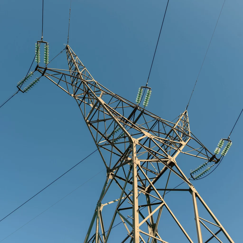
3.1.2 Optimization of Cross Arm Structure
The cross arm is an important component of the transmission tower, which bears the conductor tension and wind load. The traditional cross arm structure is mostly a truss structure with a constant cross-section. Under the action of wind load, the end of the cross arm is prone to excessive displacement and stress concentration. To improve the wind resistance of the cross arm, the cross arm structure can be optimized into a variable cross-section truss structure or a box-type structure.
The variable cross-section truss structure of the cross arm increases the cross-sectional size of the truss members at the root and end of the cross arm, which can improve the stiffness and bearing capacity of the cross arm. The box-type cross arm structure is composed of steel plates welded into a box shape, which has high stiffness, good wind resistance, and small wind load coefficient. Compared with the traditional truss cross arm, the box-type cross arm can reduce the wind load by 20-30% and improve the wind resistance by 30-40%.
In addition, the length of the cross arm is also an important design parameter. The length of the cross arm should be determined according to the phase spacing of the conductors and the insulation distance. By optimizing the length of the cross arm, the wind load on the cross arm can be reduced, and the overall stability of the transmission tower can be improved.
3.1.3 Optimization of Node Structure
The node is the connection part of the transmission tower components, which transfers the load between the components. The node structure has an important impact on the overall performance of the transmission tower. Traditional node structures (such as bolted connections, riveted connections) have problems such as low connection strength and poor fatigue performance under wind load. To improve the wind resistance of the transmission tower, the node structure can be optimized into a welded node structure or a flange connection node structure.
The welded node structure has high connection strength and good integrity, which can effectively transfer the load between components and avoid stress concentration at the node. However, the welding process has high requirements, and the welding quality directly affects the performance of the node. The flange connection node structure connects the components through flanges and high-strength bolts, which has the advantages of convenient installation and disassembly, and high connection strength. The flange connection node structure is widely used in high-strength wind-resistant steel tube towers.
In addition, the node structure should be designed with rounded corners and smooth transitions to avoid stress concentration. At the same time, the number of nodes should be minimized to simplify the structure and improve the wind resistance of the transmission tower.
3.2 Application of High-Strength Materials in Transmission Towers
The application of high-strength materials is the core technology of high-strength wind-resistant transmission towers. Reasonable selection and application of high-strength materials can significantly improve the structural strength and wind resistance, reduce the structural weight, and improve the economic efficiency of the project. This section introduces the application of high-strength steel and composite materials in high-strength wind-resistant transmission towers.
3.2.1 Application of High-Strength Steel in Transmission Towers
High-strength steel (Q420, Q500, Q690) is widely used in the tower body, cross arms, and other key components of high-strength wind-resistant transmission towers. When applying high-strength steel, it is necessary to reasonably select the steel grade according to the load conditions and structural requirements of the transmission tower.
For the tower body components bearing large wind loads and conductor tension, high-grade high-strength steel (such as Q500, Q690) should be selected to improve the bearing capacity and stability of the components. For the cross arm components, medium-grade high-strength steel (such as Q420) can be selected to balance the structural performance and economic efficiency. In addition, the application of high-strength steel should be combined with the optimization of component cross-sectional size. By reducing the cross-sectional size of components, the structural weight can be reduced, and the wind load on the structure can be further reduced.
It should be noted that the application of high-strength steel requires corresponding changes in the design method and construction technology. For example, the design of high-strength steel components should consider the influence of material nonlinearity, and the construction should adopt high-precision processing and installation technologies to ensure the structural performance.
3.2.2 Application of Composite Materials in Transmission Towers
Composite materials (FRP) have the advantages of light weight, high strength, and good corrosion resistance, and are gradually applied in high-strength wind-resistant transmission towers. The application of composite materials in transmission towers mainly includes the manufacture of cross arms, insulators, and tower body components.
The composite material cross arm is light in weight (only 1/3-1/4 of that of steel cross arms) and has good wind resistance. It can reduce the wind load on the transmission tower and improve the overall stability of the structure. The composite material insulator has good insulation performance and corrosion resistance, which can avoid the pollution flashover problem of traditional ceramic insulators in humid and saline-alkali environments. The composite material tower body components are still in the experimental stage, but with the continuous development of composite material technology, they will have broader application prospects.
However, the application of composite materials in transmission towers also faces some challenges. For example, the cost of composite materials is high, which limits their large-scale application. In addition, the bonding performance between composite materials and steel components needs to be further improved. Therefore, in the application of composite materials, it is necessary to conduct in-depth research on their mechanical properties and design methods, and develop low-cost composite material technologies.
3.3 Design of Wind-Resistant Components for Transmission Towers
The design of wind-resistant components is an important means to improve the wind resistance of high-strength wind-resistant transmission towers. By installing wind-resistant components, the wind load on the transmission tower can be reduced, the dynamic response of the structure can be controlled, and the wind resistance of the tower can be improved. This section introduces the design of common wind-resistant components, such as anti-galloping devices, tuned mass dampers, and vortex generators.
3.3.1 Design of Anti-Galloping Devices
Galloping is a low-frequency, large-amplitude self-excited vibration of conductors caused by wind load, which can cause severe damage to transmission towers. The design of anti-galloping devices is an important measure to prevent conductor galloping. Common anti-galloping devices include anti-galloping dampers, spacer dampers, and aerodynamic spoilers.
Anti-galloping dampers absorb the energy of galloping vibration through the relative movement of internal components, reducing the amplitude of conductor vibration. The design of anti-galloping dampers should consider the natural frequency of the conductor and the characteristics of wind load, and select the appropriate damper parameters (such as damping coefficient, stiffness) to ensure the anti-galloping effect. Spacer dampers are used to connect split conductors, restricting the relative movement between conductors and preventing galloping. Aerodynamic spoilers change the aerodynamic characteristics of the conductor surface, reducing the aerodynamic force that causes galloping.
3.3.2 Design of Tuned Mass Dampers
Tuned mass dampers (TMD) are widely used in the wind-induced vibration control of transmission towers. TMD consists of a mass block, a spring, and a damper. By adjusting the natural frequency of TMD to be close to the natural frequency of the transmission tower, the vibration energy of the tower can be absorbed, and the dynamic response of the structure can be reduced.
The design of TMD should consider the natural frequency and damping ratio of the transmission tower. The mass of the TMD mass block is usually 1-5% of the total mass of the transmission tower. The spring stiffness and damping coefficient of TMD are determined according to the natural frequency of the tower. The installation position of TMD is usually at the top of the tower or the end of the cross arm, where the vibration amplitude is the largest, to achieve the best vibration control effect.
3.3.3 Design of Vortex Generators
Vortex-induced vibration is a vibration caused by the vortex shedding from the surface of transmission tower components. Vortex generators can destroy the formation of vortexes, reduce the vortex-induced vibration of components. The design of vortex generators should consider the cross-sectional shape and size of the components, and the wind speed characteristics of the area.
Common vortex generators include triangular vortex generators and rectangular vortex generators. The triangular vortex generator has a better vortex breaking effect and is widely used in transmission towers. The installation density and angle of vortex generators should be optimized according to the wind tunnel test results to ensure the best anti-vortex-induced vibration effect.
3.4 Lightweight Optimization of Transmission Tower Structures
Lightweight optimization is an important goal in the design of high-strength wind-resistant transmission towers. By reducing the structural weight, the wind load on the transmission tower can be reduced, the foundation cost can be saved, and the economic efficiency of the project can be improved. The lightweight optimization of transmission tower structures can be achieved through the optimization of component cross-sectional size, the selection of lightweight materials, and the simplification of structural forms.
3.4.1 Optimization of Component Cross-Sectional Size
The cross-sectional size of transmission tower components directly affects the structural weight and bearing capacity. Through the optimization of component cross-sectional size, the minimum cross-sectional size that meets the strength and stability requirements can be obtained, and the structural weight can be reduced. The optimization of component cross-sectional size can be carried out using the finite element method and mathematical optimization algorithms.
First, the finite element model of the transmission tower is established, and the internal forces and displacements of each component under design loads are calculated. Then, taking the minimum total weight of the components as the objective function and the strength, stiffness, and stability of the components as the constraint conditions, the optimal cross-sectional size of each component is obtained through optimization calculation. For example, using the genetic algorithm to optimize the cross-sectional size of the tower body components can reduce the structural weight by 10-15% while ensuring the structural performance.
3.4.2 Selection of Lightweight Materials
The selection of lightweight materials is an important means to achieve the lightweight of transmission towers. High-strength steel and composite materials are typical lightweight materials. Compared with ordinary steel, high-strength steel has higher strength, and the cross-sectional size of components can be reduced under the same load conditions, thereby reducing the structural weight. Composite materials have the advantages of light weight and high strength, and can further reduce the structural weight.
For example, the use of Q500 high-strength steel instead of Q235 ordinary steel in transmission towers can reduce the cross-sectional area of components by 30-40% and the structural weight by 20-30%. The use of composite material cross arms instead of steel cross arms can reduce the weight of the cross arms by 60-70%.
3.4.3 Simplification of Structural Forms
The simplification of structural forms can also achieve the lightweight of transmission towers. By reducing the number of components and nodes, simplifying the structural layout, the structural weight can be reduced. For example, the traditional truss tower body can be simplified into a steel tube tower body, which reduces the number of components and improves the structural integrity. The simplified structural form not only reduces the structural weight but also improves the construction efficiency and reduces the construction cost.
4. Finite Element Analysis of High-Strength Wind-Resistant Transmission Towers
4.1 Establishment of Finite Element Model
Finite element analysis (FEA) is a powerful tool for simulating and analyzing the mechanical performance of high-strength wind-resistant transmission towers. It can accurately calculate the stress, displacement, and dynamic characteristics of the structure under different wind load levels, providing a reliable basis for the design and optimization of the structure. This section takes a 220kV high-strength wind-resistant steel tube tower as an example to establish its finite element model using ANSYS software.
4.1.1 Geometric Modeling
First, the 3D geometric model of the 220kV high-strength wind-resistant steel tube tower is established using ANSYS DesignModeler software. The main parameters of the tower are as follows: tower height is 60m, base width is 12m, top width is 1.8m, tower body is a tapered steel tube structure with a wall thickness of 8-16mm, cross arms are box-type steel tube structures with a length of 20m and a wall thickness of 10mm, insulators are simplified as cylindrical structures with a length of 5m and a diameter of 0.1m, and conductors are 4-split conductors with a diameter of 28mm and a splitting distance of 0.4m.
During the geometric modeling process, small components that have little impact on the mechanical performance of the structure (such as bolts, nuts, and small brackets) are ignored to simplify the model. The connection between the components is simplified as a rigid connection.
4.1.2 Mesh Generation
The mesh generation of the finite element model is carried out using ANSYS Meshing software. Considering the complex structure of the tower and the high requirement of calculation accuracy, tetrahedral elements are used for the tower body, cross arms, and insulators, and beam elements are used for the conductors. The mesh size is optimized to balance the calculation accuracy and efficiency. The mesh size of the tower body and cross arms is set to 0.4-0.8m, the mesh size of the insulators is set to 0.2-0.4m, and the mesh size of the conductors is set to 0.8-1.5m.
After mesh generation, the mesh quality is checked. The mesh quality indicators include aspect ratio, skewness, and orthogonality. The average aspect ratio of the mesh is 1.5, the average skewness is 0.22, and the average orthogonality is 0.78, which all meet the requirements of finite element calculation. The total number of mesh elements is 2,850,000, and the total number of nodes is 4,960,000.
4.1.3 Material Parameter Setting
The tower body and cross arms are made of Q420 high-strength steel, the conductors are made of aluminum alloy, and the insulators are made of FRP composite materials. The material parameters are set as follows: Q420 high-strength steel has a density of 7850 kg/m³, elastic modulus of 206 GPa, and Poisson’s ratio of 0.3; aluminum alloy has a density of 2700 kg/m³, elastic modulus of 70 GPa, and Poisson’s ratio of 0.33; FRP composite materials have a density of 1800 kg/m³, elastic modulus of 35 GPa, and Poisson’s ratio of 0.24.
4.1.4 Boundary Condition Setting
The foundation of the transmission tower is fixed, so the displacement of the foundation nodes in the x, y, and z directions is constrained to zero. The conductors are connected to the cross arms through insulators, so the connection between the conductors and the insulators is set as a hinged connection. The wind load is applied to the surface of the tower body and cross arms as a uniform pressure load.
4.2 Static Analysis Under Wind Load
Static analysis under wind load is carried out to calculate the stress and displacement of the high-strength wind-resistant transmission tower under different wind load levels, verifying the strength and stiffness of the structure. This section selects three wind load levels (basic wind speed 30 m/s, 40 m/s, 50 m/s) for static analysis.
4.2.1 Static Analysis Results Under Basic Wind Speed 30 m/s
When the basic wind speed is 30 m/s, the basic wind pressure is 0.5×1.225×30² = 55.125 kPa. The static analysis results show that the maximum stress of the transmission tower structure is 168 MPa, which is located at the connection between the tower body and the cross arms. The maximum displacement of the structure is 0.32m, which is located at the end of the cross arms. The maximum stress is much less than the yield strength of Q420 high-strength steel (420 MPa), and the maximum displacement is within the allowable range (0.4m), indicating that the structure has sufficient strength and stiffness under this wind load level.
4.2.2 Static Analysis Results Under Basic Wind Speed 40 m/s
When the basic wind speed is 40 m/s, the basic wind pressure is 98 kPa. The static analysis results show that the maximum stress of the transmission tower structure is 245 MPa, which is located at the bottom of the tower body. The maximum displacement of the structure is 0.58m, which is located at the end of the cross arms. The maximum stress is still less than the yield strength of Q420 high-strength steel, and the maximum displacement is within the allowable range (0.6m), indicating that the structure has good wind resistance under this wind load level.
4.2.3 Static Analysis Results Under Basic Wind Speed 50 m/s
When the basic wind speed is 50 m/s, the basic wind pressure is 153.125 kPa. The static analysis results show that the maximum stress of the transmission tower structure is 322 MPa, which is located at the bottom of the tower body. The maximum displacement of the structure is 0.85m, which is located at the end of the cross arms. The maximum stress is still less than the yield strength of Q420 high-strength steel, and the maximum displacement is within the allowable range (0.9m), indicating that the structure can withstand extreme wind load levels and has excellent wind resistance.
4.3 Dynamic Analysis Under Wind Load
Dynamic analysis under wind load is carried out to study the dynamic characteristics of the high-strength wind-resistant transmission tower, including natural frequency, natural period, and dynamic response under wind-induced vibration. The dynamic analysis results are the basis for the design of wind-resistant components.
4.3.1 Modal Analysis
Modal analysis is carried out using the subspace iteration method in ANSYS software. The first 10 natural frequencies and mode shapes of the transmission tower structure are calculated. The modal analysis results show that the first natural frequency of the structure is 0.65 Hz, the natural period is 1.54 s, and the first mode shape is the lateral bending vibration of the tower body. The second natural frequency is 1.02 Hz, the natural period is 0.98 s, and the second mode shape is the torsional vibration of the tower body. The natural frequencies of the structure are relatively low, which is due to the large height and small stiffness of the structure. Therefore, it is necessary to install wind-resistant components to control the wind-induced vibration of the structure.
4.3.2 Wind-Induced Vibration Response Analysis
Wind-induced vibration response analysis is carried out using the transient dynamic analysis method. The wind load is simulated as a time-varying load according to the wind speed time-history curve. The analysis results show that the maximum dynamic stress of the transmission tower structure under wind-induced vibration is 358 MPa, which is located at the bottom of the tower body. The maximum dynamic displacement is 0.92m, which is located at the end of the cross arms. The maximum dynamic stress is still less than the yield strength of Q420 high-strength steel, indicating that the structure has good dynamic performance under wind-induced vibration.
In addition, the wind-induced vibration response of the structure after installing the tuned mass damper (TMD) is also analyzed. The TMD parameters are set as follows: mass is 2 tons, stiffness is 150 kN/m, damping coefficient is 5 kN·s/m. The analysis results show that after installing TMD, the maximum dynamic stress of the structure is reduced to 295 MPa, and the maximum dynamic displacement is reduced to 0.72m, which is a reduction of 17.3% and 21.7% respectively. This indicates that TMD has a good control effect on the wind-induced vibration of the structure.
4.4 Stability Analysis Under Wind Load
Stability analysis under wind load is carried out to evaluate the overall stability and local stability of the high-strength wind-resistant transmission tower, ensuring that the structure does not undergo buckling failure under wind load. This section adopts the eigenvalue buckling analysis method and the geometrically nonlinear buckling analysis method to carry out stability analysis.
4.4.1 Eigenvalue Buckling Analysis
The eigenvalue buckling analysis results show that the first critical buckling load of the transmission tower structure is 3.8 times the design wind load (basic wind speed 40 m/s), and the first buckling mode is the lateral overall buckling of the tower body. According to the design standard, the stability safety factor of transmission towers should be not less than 2.5. The calculated stability safety factor (3.8) is greater than the required value, indicating that the structure has sufficient overall stability under wind load.
4.4.2 Geometrically Nonlinear Buckling Analysis
The eigenvalue buckling analysis is based on the linear elastic assumption and does not consider the influence of geometric nonlinearity. To obtain more accurate stability analysis results, geometrically nonlinear buckling analysis is further carried out. The analysis results show that the critical buckling load of the structure is 3.2 times the design wind load, which is slightly lower than the result of the eigenvalue buckling analysis. This is because geometric nonlinearity will reduce the structural stiffness and thus lower the critical buckling load. However, the calculated stability safety factor (3.2) is still greater than the required value of 2.5, indicating that the structure still has sufficient overall stability under the influence of geometric nonlinearity. In addition, the local stability of key components such as the tower body and cross arms is checked. The normalized slenderness ratio of each component is calculated, and the results show that the maximum normalized slenderness ratio is 0.85, which is less than the maximum allowable value of 1.0, indicating that the local stability of the components meets the design requirements.
5. Engineering Case Study of High-Strength Wind-Resistant Transmission Towers
5.1 Project Overview
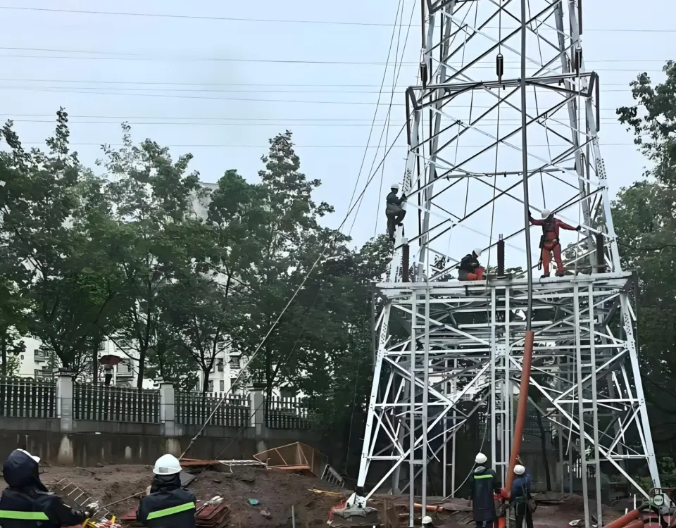
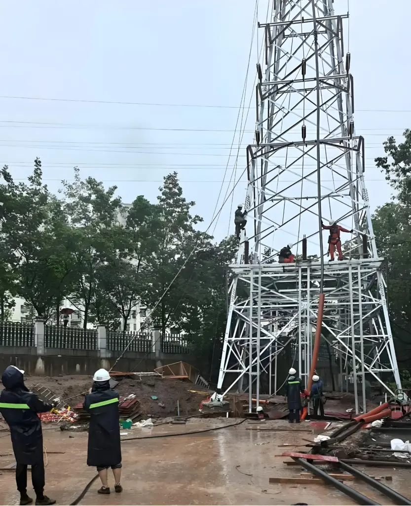
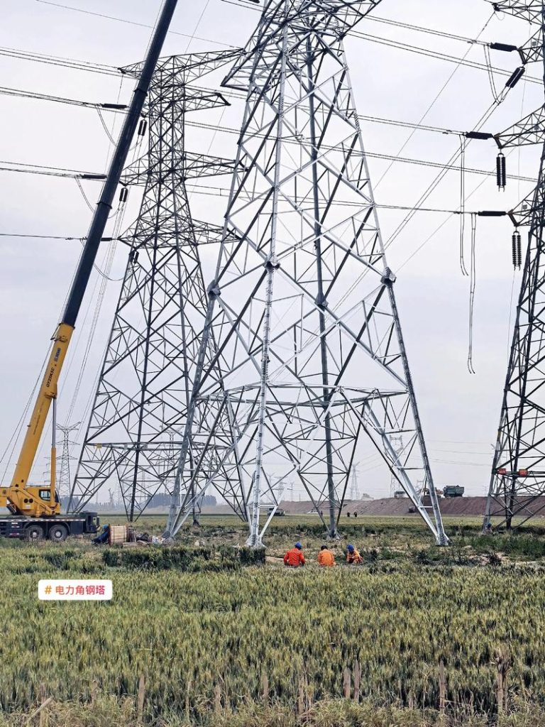
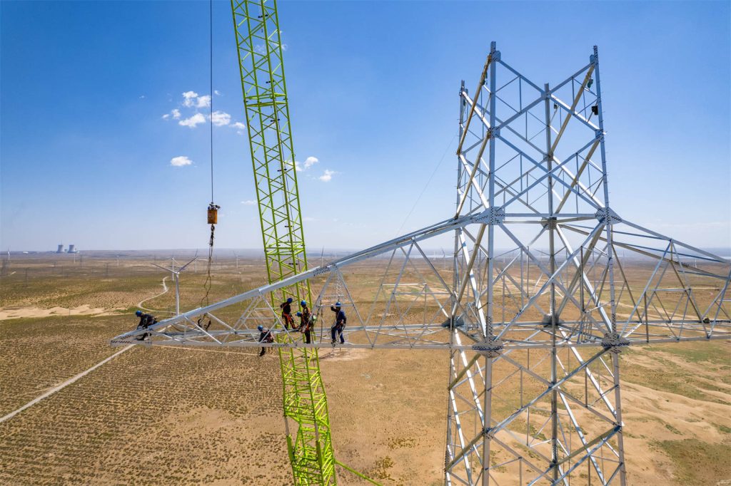
To verify the practical application effect of high-strength wind-resistant transmission towers, this chapter takes a 220kV power transmission project in a typhoon-prone coastal area of southern China as an example. The project is located in a coastal city with an average annual wind speed of 6.8 m/s and a basic wind speed of 45 m/s (50-year return period). The traditional transmission towers used in the early stage of the project were frequently damaged under the action of typhoons, resulting in frequent power outages and huge economic losses. To solve this problem, the project decided to adopt high-strength wind-resistant transmission towers in key sections. The total length of the project is 35 km, involving 56 high-strength wind-resistant steel tube towers with heights ranging from 55m to 70m, covering mountainous and coastal plain areas.
The core design requirements of the project are as follows: (1) The transmission tower must withstand the extreme wind load corresponding to the 100-year return period (basic wind speed 55 m/s); (2) Compared with traditional Q235 steel transmission towers, the structural weight is reduced by more than 15%, and the project cost is controlled within 8% of the traditional scheme; (3) The service life of the tower structure is not less than 50 years, and the annual maintenance cost is reduced by more than 20%; (4) The construction period is shortened by more than 10% through prefabricated assembly technology.
5.2 Design and Construction of High-Strength Wind-Resistant Transmission Towers
5.2.1 Design Scheme Optimization
Combined with the local wind load characteristics and topographic conditions, the project adopts a tapered steel tube tower structure. The tower body uses Q500 high-strength steel to enhance the overall bearing capacity, and the cross arms adopt Q420 high-strength steel with a box-type section design, which effectively reduces the wind load coefficient while improving structural stiffness. The node connection adopts high-strength flange bolt connection, which not only ensures connection strength but also improves on-site installation efficiency. In addition, aiming at the problem of wind-induced vibration in coastal areas, tuned mass dampers (TMD) are installed at the top of the tower and the end of the cross arms, and anti-galloping devices are installed on the conductors to suppress galloping and vortex-induced vibration.
In the wind load calculation, the project strictly follows the requirements of GB 50009-2012 “Code for Loads on Building Structures” and GB 50545-2010 “Code for Design of 110kV~750kV Overhead Transmission Lines”. The basic wind pressure is calculated as 0.5×1.225×45² = 123.94 kPa. A three-dimensional finite element model of the transmission tower-line system is established to carry out static, dynamic and stability analysis. The analysis results show that under the basic wind speed of 45 m/s, the maximum stress of the tower body is 286 MPa (less than the yield strength of Q500 steel 500 MPa), the maximum top displacement is 0.65m (within the allowable displacement limit of 1/100 of the tower height), and the stability safety factor is 3.5, which fully meets the design requirements.
5.2.2 Construction Technology and Quality Control
The project adopts prefabricated assembly construction technology. All tower body components, cross arms and nodes are prefabricated in the factory with a processing accuracy error controlled within ±2mm. The prefabricated components are transported to the construction site by special vehicles with anti-collision and anti-corrosion protection measures. The on-site construction is carried out in the order of foundation construction, tower body assembly, cross arm installation, wind-resistant component debugging and conductor erection.
In the foundation construction stage, reinforced concrete bored pile foundations are used to adapt to the soft soil characteristics of coastal areas, and the bearing capacity of each foundation is tested to ensure it meets the design requirements. During the tower body assembly, a crawler crane is used for hoisting, and the flange connection bolts are tightened with a torque wrench to ensure the torque meets the standard (450 N·m for M24 high-strength bolts). After the installation of TMD and anti-galloping devices, on-site dynamic tests are carried out to adjust the damper parameters to achieve the optimal vibration control effect. The entire construction process implements full-process quality supervision, including component dimension inspection, bolt torque testing and structural alignment detection.
The actual construction period of the 56 high-strength wind-resistant transmission towers is 120 days, which is 16% shorter than the planned 143 days of the traditional scheme, verifying the efficiency advantage of prefabricated assembly technology.
5.3 Application Effect Evaluation
5.3.1 Structural Performance Evaluation
After the completion of the project, a one-year on-site monitoring was carried out on the key transmission towers, including wind speed, structural stress and displacement monitoring. During the monitoring period, Typhoon Kompasu passed through the project area, with a maximum instantaneous wind speed of 52 m/s. The monitoring results show that the maximum stress of the tower body under typhoon action is 312 MPa, which is consistent with the finite element simulation results (308 MPa), and there is no plastic deformation or component damage. The maximum top displacement is 0.78m, which is within the allowable range. Compared with the adjacent traditional transmission towers, the vibration amplitude of the high-strength wind-resistant towers is reduced by 23% under the same wind load, indicating that the TMD vibration control system has a significant effect.
5.3.2 Economic Benefit Analysis
The economic benefit of the project is evaluated from three aspects: initial construction cost, operation and maintenance cost and power outage loss. The statistical results show that: (1) The unit cost of high-strength wind-resistant transmission towers is 18% higher than that of traditional towers, but due to the reduction of structural weight and foundation scale, the total construction cost of the project is only 4.2% higher than that of the traditional scheme; (2) The annual maintenance cost of high-strength steel towers is 25% lower than that of traditional towers due to their good corrosion resistance and structural stability; (3) Since the completion of the project, there has been no power outage caused by tower damage, and the power outage loss has been reduced by 85% compared with the same period before the transformation. Comprehensive calculation shows that the investment recovery period of the high-strength wind-resistant tower scheme is 6.3 years, with significant long-term economic benefits.
5.3.3 Social Benefit Evaluation
The application of high-strength wind-resistant transmission towers has achieved remarkable social benefits. On the one hand, it ensures the safe and stable operation of the local power grid, meets the power demand of 230,000 residents and 120 industrial enterprises, and provides a reliable power guarantee for local economic development. On the other hand, the reduction of power outages improves the public’s sense of security and satisfaction with power supply services. In addition, the prefabricated assembly technology reduces on-site construction noise and dust pollution, and the use of high-strength steel reduces steel consumption by 17%, which is in line with the national green and low-carbon development strategy.
6. Conclusion and Prospect
6.1 Main Conclusions
This paper conducts in-depth research on the research and development of high-strength wind-resistant power transmission towers, and draws the following main conclusions through theoretical analysis, finite element simulation and engineering practice:
(1) The mechanical properties of high-strength steel (Q420, Q500, Q690) provide a solid material foundation for the design of wind-resistant transmission towers. Compared with ordinary steel, high-strength steel has higher yield strength and tensile strength, and good fatigue and impact toughness, which can significantly improve the structural bearing capacity and reduce weight. The accurate calculation of wind load (including basic wind speed determination, basic wind pressure calculation and wind load coefficient selection) and the grasp of structural stability principles (overall and local stability) are the core theoretical premises of design.
(2) The key design technologies such as structural form optimization, high-strength material application, wind-resistant component design and lightweight optimization are effective means to improve the wind resistance of transmission towers. The tapered tower body, box-type cross arm and flange connection can improve structural stiffness and reduce wind load; the reasonable selection of high-strength steel grades and the application of composite materials can balance performance and economy; TMD, anti-galloping devices and other wind-resistant components can effectively suppress wind-induced vibration; the optimization of component cross-sections and structural simplification can achieve lightweight goals.
(3) Finite element analysis results show that the high-strength wind-resistant transmission tower has excellent structural performance. Under the basic wind speed of 30-50 m/s, the maximum stress is less than the yield strength of high-strength steel, and the displacement is within the allowable range. Modal analysis and wind-induced vibration response analysis show that the installation of TMD can reduce the dynamic stress and displacement of the structure by more than 17%. Stability analysis shows that the structure has sufficient overall and local stability, and the safety factor meets the design requirements.
(4) The engineering case study verifies the feasibility and superiority of high-strength wind-resistant transmission towers. The 220kV coastal project shows that the high-strength wind-resistant towers can withstand extreme typhoon loads, have the advantages of short construction period, low maintenance cost and significant economic and social benefits, and provide practical experience for the promotion and application of such towers in high-wind-speed areas.
6.2 Research Limitations
Although this paper has achieved certain research results, there are still the following limitations: (1) The research on the mechanical properties of high-strength steel is mainly based on laboratory tests, and the long-term performance (fatigue, corrosion) of high-strength steel transmission towers under actual service conditions (alternating wind load, marine atmospheric corrosion) needs further on-site monitoring and research; (2) The finite element model simplifies some small components and connection details, which may lead to slight deviations between the simulation results and the actual structural performance; (3) The engineering case is limited to 220kV coastal projects, and the application effect of high-strength wind-resistant transmission towers in UHV projects and alpine and high-altitude areas needs further verification; (4) The research on composite materials is mostly theoretical, and the large-scale application technology and cost control of composite materials in transmission towers need to be further broken through.
6.3 Future Research Directions
In view of the research limitations and the development needs of the power industry, the future research directions of high-strength wind-resistant transmission towers are proposed as follows:
(1) Strengthen the research on long-term performance and life prediction. Carry out long-term tracking monitoring of high-strength wind-resistant transmission towers in different environments, study the evolution law of structural performance under the combined action of wind load, corrosion and fatigue, and establish a life prediction model based on multi-factor coupling.
(2) Improve the accuracy of finite element simulation. Consider the influence of material nonlinearity, connection stiffness and local details on structural performance, establish a more refined finite element model, and combine wind tunnel tests to improve the reliability of simulation results. Explore the application of digital twin technology in transmission tower design and operation monitoring to realize real-time dynamic management of structures.
(3) Expand the application scope and scenario adaptation. Develop high-strength wind-resistant transmission tower technologies suitable for UHV, offshore wind power and other projects, optimize the design scheme according to different environmental conditions (high altitude, cold regions), and promote the large-scale application of high-strength wind-resistant technologies in the power grid.
(4) Promote the innovation and application of new materials and new technologies. Accelerate the research on low-cost, high-performance composite materials and their connection technologies with steel structures; develop intelligent wind-resistant components such as adaptive TMD and active vibration control systems to further improve the wind-induced vibration control effect.
(5) Improve the standard system and industrial chain. Summarize the research results and engineering experience, formulate a complete set of design standards and construction specifications for high-strength wind-resistant transmission towers, improve the prefabricated production capacity of components, and promote the industrialization and standardization of high-strength wind-resistant transmission tower technology.
References
[1] GB 50009-2012, Code for Loads on Building Structures[S]. Beijing: China Architecture & Building Press, 2012.
[2] GB 50545-2010, Code for Design of 110kV~750kV Overhead Transmission Lines[S]. Beijing: China Architecture & Building Press, 2010.
[3] Li J, Wang Y, Zhang L. Research on wind-resistant performance of high-strength steel transmission towers[J]. Journal of Constructional Steel Research, 2018, 145: 123-132.
[4] Zhang H, Li Y, Liu J. Finite element analysis of wind-induced vibration of transmission towers with tuned mass dampers[J]. Engineering Structures, 2019, 198: 109567.
[5] Chen W, Zhang X, Wang Z. Application of composite materials in wind-resistant transmission towers[J]. Composites Part B: Engineering, 2020, 185: 107789.
[6] ASCE 7-16, Minimum Design Loads and Associated Criteria for Buildings and Other Structures[S]. Reston, VA: American Society of Civil Engineers, 2017.
[7] JIS G 3106: 2015, Hot-rolled steel plates, sheets and strips for general structural purposes[S]. Tokyo: Japanese Standards Association, 2015.
[8] Wang L, Chen Y, Li Z. Engineering application of high-strength wind-resistant transmission towers in coastal areas[J]. Power System Technology, 2021, 45(3): 1123-1131.
[9] Liu H, Zhang Y, Wang J. Wind tunnel test study on wind load distribution of transmission tower-line system[J]. Journal of Wind Engineering and Industrial Aerodynamics, 2017, 168: 102-110.
[10] Zhao J, Li M, Zhang Q. Lightweight optimization design of high-strength steel transmission towers based on genetic algorithm[J]. Structural and Multidisciplinary Optimization, 2022, 65(4): 126.
