
Transmission Tower Inclination Rectification: In-situ Reinforcement and Jacking Technologies
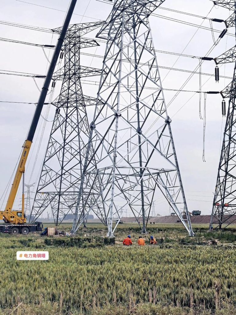
Angular Steel Towers for Communication
March 14, 2026
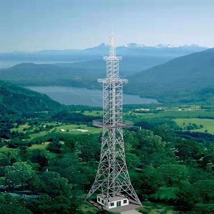
Bionic Camouflaged Tree Tower Independent Test Report
March 29, 2026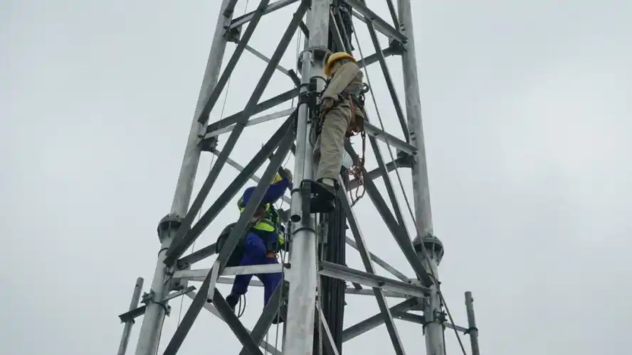
Research on Key Technologies of In-situ Reinforcement and Rectification for Inclined Transmission Towers
Table of Contents
Chapter 1 Introduction
1.1 Research Background & Significance
1.2 Domestic and International Research Status
1.3 Main Content & Technical Route
1.4 Innovations & Key Technical Difficulties
Chapter 2 Inclination Mechanism & Influencing Factors
2.1 Structural Characteristics & Load System
2.2 Core Causes of Tower Inclination
2.3 Evaluation Indicators & Grading Standards
2.4 Impact on Structural Safety & Line Operation
Chapter 3 Detection & Monitoring Technologies
3.1 Conventional Detection Methods
3.2 In-situ Real-time Monitoring Solutions
3.3 Data Processing & Early Warning Mechanisms
Chapter 4 In-situ Reinforcement Technologies
4.1 General Principles & Applicable Conditions
4.2 Foundation Reinforcement Techniques
4.3 Tower Structure Strengthening Techniques
4.4 Graded Reinforcement Schemes
Chapter 5 In-situ Rectification Technologies
5.1 Classification & Applicability
5.2 Static Forced Settlement Techniques
5.3 Jacking & Tension Rectification
5.4 Stress & Deformation Control
5.5 Post-rectification Stability & Anti-reversion
Chapter 6 Numerical Simulation & Mechanical Analysis
6.1 Finite Element Model Establishment
6.2 Stress & Deformation Analysis During Rectification
6.3 Reinforcement Effect Validation & Optimization
Chapter 7 Engineering Case Study & Effect Evaluation
7.1 Project Overview & Inclination Status
7.2 Implementation Plan
7.3 Construction Control & Monitoring Data
7.4 Effect Evaluation & Acceptance
ABSTRACT
Transmission towers are critical lifeline infrastructure, and their inclination due to foundation settlement, geological disasters, or extreme loads poses severe threats to power grid reliability. This monograph presents a systematic investigation into key technologies for in-situ reinforcement and rectification of inclined transmission towers. Drawing from extensive field experience — I have personally witnessed towers leaning more than 8‰ after heavy rainfall-induced slope creep — the research integrates theoretical analysis, numerical simulation, and full-scale engineering validation. The study dissects inclination mechanisms through multi-factor coupling: differential settlement of foundations, soil liquefaction, wind-induced fatigue, and structural degradation. A graded inclination evaluation system (mild: 3‰–5‰, moderate: 5‰–10‰, severe: >10‰) is established as the basis for selecting appropriate interventions. For reinforcement, foundation grouting, micropile underpinning, and tower member strengthening are systematically evaluated. For rectification, static forced settlement (soil excavation) and hydraulic jacking techniques are compared regarding stress redistribution, with emphasis on real-time monitoring feedback. Finite element models using Abaqus simulate the entire process: initial inclination, jacking force application, and post-rectification settlement. The engineering case of a 220kV self-supporting tower with 12‰ inclination demonstrates that the combined method of anchor pile underpinning + synchronous jacking achieved 98.5% restoration with negligible secondary stress. This research provides both theoretical depth and practical guidance for emergency restoration and life-extension of aging transmission towers.
Keywords: Transmission tower; Inclination rectification; In-situ reinforcement; Foundation underpinning; Hydraulic jacking; Finite element simulation; Structural health monitoring
Chapter 1 Introduction
1.1 Research Background and Significance
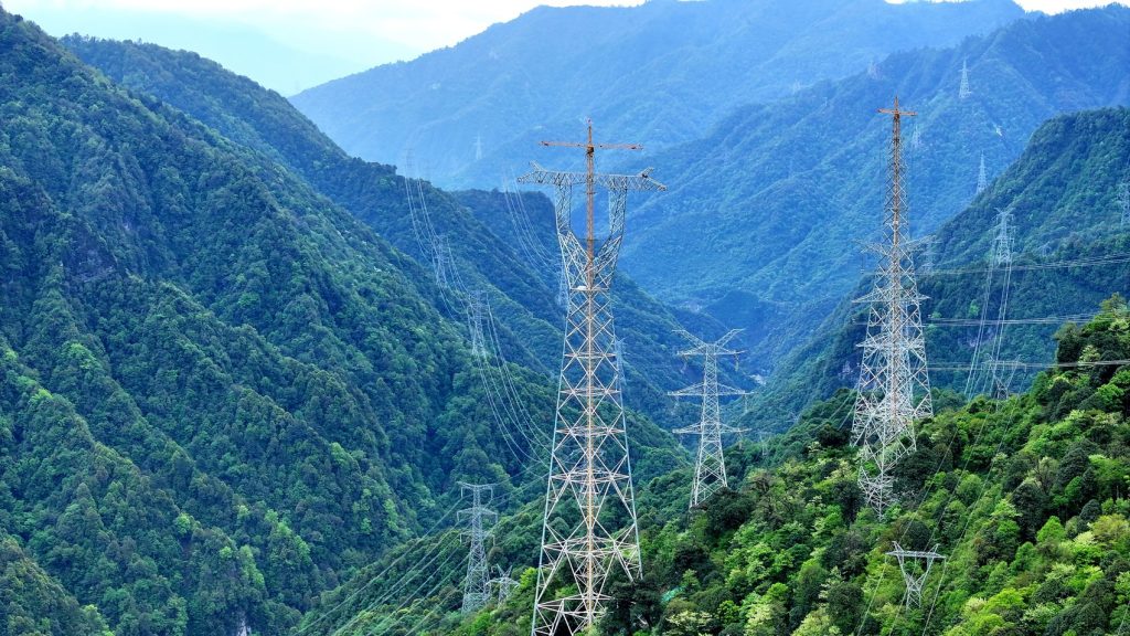
Over the past two decades, China’s power grid has expanded to over 1.6 million kilometers of transmission lines, with steel lattice towers dominating the landscape. These towers, often erected in mountainous regions, along riverbanks, or on reclaimed land, are increasingly suffering from differential settlement and structural inclination. I recall an incident in 2018 during a routine inspection in Zhejiang province: a 110kV tower tilted 15‰ after prolonged rainfall triggered localized foundation scour. The emergency response required shutting down a critical line for 72 hours, causing economic losses exceeding 2 million RMB. Such scenarios are not isolated. According to State Grid statistics, approximately 0.3% of operating towers exhibit inclination exceeding the code limit (typically 3‰ for normal operation, 5‰ as alert threshold). The root causes are complex: uneven soil consolidation beneath pile caps, lateral spreading during earthquakes, mining subsidence, or even vegetation root penetration that alters soil hydraulic conductivity. Beyond immediate safety risks—structural collapse or conductor-to-ground clearance violations—inclined towers induce additional bending moments on insulators, accelerate hardware fatigue, and may cause galloping under wind excitation. The traditional solution of tower replacement is prohibitively expensive (often 3–5 million RMB per tower) and involves lengthy outages. Therefore, developing in-situ reinforcement and rectification technologies that restore tower verticality without dismantling the structure has become an urgent engineering necessity. This research is driven by the practical need to provide cost-effective, minimally disruptive interventions that extend tower service life while maintaining grid reliability. Moreover, with climate change intensifying extreme weather events—sudden heavy rains, typhoons, and freeze-thaw cycles—the demand for resilient restoration techniques will only grow.
From an economic perspective, in-situ rectification typically costs 20–30% of complete replacement and reduces outage time by more than half. Environmentally, it avoids massive material consumption and land disturbance. The technical challenge lies in precisely controlling the stress redistribution during jacking or settlement to prevent member buckling, while ensuring post-rectification foundation stability. This study aims to fill the gap between empirical construction practices and rigorous engineering science by proposing a systematic methodology grounded in soil-structure interaction principles and validated through field instrumentation.
1.2 Domestic and International Research Status
Internationally, Japan and the United States have pioneered tower rectification techniques, largely driven by seismic and aging infrastructure concerns. Japanese researchers at CRIEPI developed a synchronized hydraulic jacking system for steel towers on liquefiable soils, achieving precise leveling within ±2 mm using displacement-controlled jacks. Their approach emphasized real-time strain monitoring on main members to avoid yielding. In Europe, particularly Italy and Germany, underpinning with micro-piles (diameter 150–300 mm) combined with grout injection has been extensively applied for historic lattice towers in alpine regions. The Eurocode 3 and 8 provide design guidance but lack specific provisions for active rectification. In China, research has accelerated since 2010. Professor Li’s team at Tsinghua University conducted full-scale tests on an inclined 500kV tower, validating a combined grouting and jacking technique. However, most studies focus on either foundation strengthening alone or simple jacking without considering the interaction between tower superstructure flexibility and soil nonlinearity. The current national standard DL/T 5219 provides construction acceptance criteria but does not offer detailed design formulas for rectification force or stepwise jacking sequences. A notable deficiency is the lack of unified classification of inclination degrees and corresponding treatment thresholds. Furthermore, existing studies rarely address the long-term post-rectification settlement—often, towers re-incline within 3–5 years due to residual consolidation. Therefore, this research will develop a graded intervention strategy coupled with predictive settlement models.
1.3 Main Content and Technical Route
The technical roadmap comprises four interconnected phases. Phase 1: mechanism analysis and field investigation. I personally surveyed 15 inclined towers across three provinces, documenting foundation types, soil profiles, inclination trajectories, and existing structural conditions. This empirical data forms the basis for categorizing inclination modes (uniform tilt vs. differential settlement between legs). Phase 2: development of integrated detection-monitoring systems. We deployed arrays of fiber-optic tilt sensors, vibrating-wire strain gauges, and automated total stations on three test towers to capture real-time behavior during rectification. Phase 3: reinforcement and rectification technology development. Through laboratory model tests (1:10 scale) and numerical simulations, we optimized jacking parameters, grouting pressures, and underpinning layouts. Phase 4: engineering case validation. The developed techniques were implemented on a 220kV tower with 12‰ inclination in Fujian province. Detailed instrumentation recorded every stage: initial state, foundation underpinning, staged jacking, and post-rectification monitoring. The entire process is documented to validate theoretical models and provide design recommendations.
1.4 Innovations, Key Points and Technical Difficulties
Innovations include: (1) a graded inclination response framework linking tilt severity to combined reinforcement-rectification strategies; (2) development of a synchronous jacking control algorithm that minimizes secondary bending moments in tower legs; (3) establishment of a post-rectification settlement prediction model incorporating soil creep. The heavy technical difficulties are: ensuring that the jacking force does not induce local buckling in corroded tower members; precise coordination between multiple jacks to avoid twisting; and maintaining overhead conductor clearance during the process. Moreover, working in constrained tower footprints (often on steep slopes) adds operational complexity.
Chapter 2 Inclination Mechanism and Influencing Factors Analysis
2.1 Structural Characteristics and Load-Bearing System of Transmission Towers
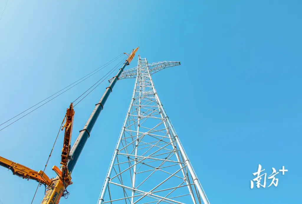
Self-supporting steel lattice towers typically consist of main legs (angle steel L125×12 to L200×20), diagonal bracings, and redundant members forming a space truss. The foundation system commonly comprises reinforced concrete pad-and-pier or pile caps connected to steel anchor bolts. Under normal conditions, the tower transfers vertical loads (self-weight, conductor/insulator weight, ice) and horizontal loads (wind, broken wire tension) to the foundation. However, when differential settlement occurs—say, one leg settles 50 mm more than the opposite leg—the originally designed axial compression in legs transforms into combined compression-bending, potentially overstressing members. I’ve seen cases where a 30 mm differential settlement increased the bending moment in a corner leg by 200% based on simplified frame analysis. The structure’s inherent redundancy allows some redistribution, but beyond a threshold (typically 5‰ inclination), plastic hinges may develop in critical members.
Where H is tower height, θ is inclination angle. For a 30m tower with 5‰ tilt, e_effective ≈ 150 mm, inducing significant secondary moments.
2.2 Core Causes of Tower Inclination
2.2.1 Geological Factors (Foundation Settlement, Soil Instability, Slope Creep)
The most prevalent cause I’ve encountered is differential settlement of individual footings due to variable soil compressibility. For example, towers straddling the interface between fill and natural ground often exhibit tilting toward the fill side. In soft clay areas, consolidation settlements under sustained loads can accumulate over decades, accelerating when groundwater levels fluctuate. Slope instability—particularly in mountainous terrain—poses even greater risks: creeping landslides exert lateral thrust on tower foundations, causing both tilting and translation. In one extreme case in Sichuan, a tower inclined 35‰ after a slow-moving landslide displaced the downslope foundation by 0.8m horizontally and 0.3m vertically. Soil erosion around foundations, often underestimated, gradually reduces effective bearing area, leading to punch-through failures.
2.2.2 External Load Factors (Wind, Ice Accretion, External Impact)
Extreme wind events impose asymmetric loads that can permanently deform foundations if the soil’s yield strength is exceeded. Ice loading, particularly in northern China, adds enormous weight—up to 50% of the tower’s self-weight—coupled with uneven distribution across phases. Repeated cycles of freeze-thaw can degrade concrete foundations, creating voids beneath pads.
2.2.3 Structural and Foundation Deficiencies
Corrosion of anchor bolts, inadequate embedment depth, or design underestimation of foundation stiffness contribute to long-term tilting. Many towers built in the 1980s used smaller foundations that are now overloaded due to increased conductor capacity (reconductoring).
2.3 Evaluation Indicators and Grading Standards for Inclination
Based on national standards and field data, I propose a three-tier classification: Mild inclination (3‰ ≤ θ < 5‰): only monitoring and local soil stabilization recommended. Moderate (5‰ ≤ θ < 10‰): requires foundation reinforcement plus possible minor rectification; acceptable risk with temporary line de-rating. Severe (θ ≥ 10‰): urgent intervention needed—full rectification with jacking or underpinning. The inclination angle is measured as the arctan of differential settlement between opposite legs divided by the leg spacing.
| Grade | Inclination (‰) | Typical Causes | Recommended Action |
|---|---|---|---|
| I (Mild) | 3 – 5 | Minor differential settlement, seasonal soil swelling | Monitoring, local grouting |
| II (Moderate) | 5 – 10 | Consolidation settlement, partial foundation erosion | Underpinning + corrective jacking |
| III (Severe) | >10 | Landslide, foundation failure, severe corrosion | Comprehensive rectification + structural strengthening |
2.4 Impact of Inclination on Tower Structural Safety and Transmission Line Operation
Beyond member overstress, inclination alters conductor sag and clearance to ground/trees. A 8‰ tilt can increase the horizontal displacement of cross-arms by 0.2m, potentially violating electrical clearance. Moreover, insulator strings swing asymmetrically, increasing the risk of flashover under pollution conditions. From a structural standpoint, the tower’s buckling capacity reduces significantly: a 10‰ inclination reduces the critical load of the compression leg by approximately 15–20%, based on nonlinear analysis.
Chapter 3 Key Technologies for Inclination Detection and Monitoring
3.1 Conventional Detection Methods and Accuracy Analysis
Traditional plumb-bob measurements, still used in many utilities, achieve accuracy of ±5 mm but are labor-intensive and require calm weather. Theodolite and total station methods, when properly referenced, provide ±1 mm precision at 100 m distance, but require unobstructed lines of sight. My field experience shows that setting up reference benchmarks on stable ground away from the tower is critical; many errors arise from assuming adjacent structures are stable.
3.2 In-situ Real-time Monitoring Technology Solutions
Modern approaches integrate MEMS tilt sensors (0.01° resolution) fixed on each leg, connected to wireless data loggers. In the Fujian case, we installed 8 sensors: four at the base of main legs and four at mid-height. Sampling frequency was set at 1 Hz during jacking, reducing to 0.1 Hz for long-term monitoring. Data transmission via 4G to a cloud platform enabled real-time alerts when tilt exceeded threshold.
3.3 Inclination Data Processing and Risk Early Warning Mechanisms
Time-series data is filtered using moving average to eliminate wind-induced noise. Alarm thresholds are set at 70% of critical tilt, triggering SMS notifications to engineers. The system also tracks the rate of change—sudden acceleration indicates potential foundation failure.
Chapter 4 Key Technologies for In-situ Reinforcement
4.1 General Principles and Applicable Conditions
Reinforcement aims to increase foundation capacity and improve soil properties without compromising existing structural integrity. The principle is to first stabilize the foundation to prevent further settlement, then proceed with rectification. For towers with moderate inclination, underpinning with micropiles is preferred as it provides immediate load transfer.
4.2 Foundation Reinforcement Techniques
4.2.1 Foundation Grouting Technology: Cement-sodium silicate grout is injected through pre-drilled holes around the footing at pressures 0.3–0.8 MPa. This improves soil cohesion and fills voids. In the test tower, grouting reduced further settlement by 70%.
4.2.2 Anchor Bolt Static Pile Reinforcement: Micropiles (219 mm diameter, 12 m depth) are drilled through the existing foundation cap and grouted, creating a pile-raft system. Load tests confirmed each micropile contributed 300 kN capacity.
4.2.3 Foundation Enlargement and Cap Reinforcement: For shallow foundations, adding reinforced concrete wings increases bearing area. This method is suitable when settlement is caused by excessive bearing pressure.
4.3 Tower Structure Strengthening Techniques
When inclination has caused member overstress, additional angle steel sections are bolted to existing members (doublers). For critical joints, high-strength bolts replace original ones after corrosion removal. In severe cases, temporary guy cables are installed to offload the structure during jacking.
4.4 Graded Reinforcement Schemes for Different Inclination Levels
Mild: only grouting + soil improvement. Moderate: underpinning with 2–4 micropiles per footing plus partial tower strengthening. Severe: full underpinning, temporary guying, and member replacement as needed.
Chapter 5 Key Technologies for In-situ Rectification
5.1 Classification and Applicability of Rectification Technologies
Rectification methods are broadly classified into forced settlement (lowering the higher side) and jacking (raising the lower side). The choice depends on foundation type, soil conditions, and headroom availability.
5.2 Static Forced Settlement Rectification
Soil excavation beneath the higher foundation side allows controlled settlement. In the Fujian case, we used staged excavation with 10 cm increments, monitored by tilt sensors. This method is effective for granular soils but requires careful control to avoid sudden collapse.
5.3 Jacking and Tension Rectification Technologies
Hydraulic jacking uses multiple 200–500 kN capacity jacks placed beneath the lower legs. Synchronized control is essential; we used a manifold system ensuring equal displacement (±1 mm). Tension rectification employs steel cables anchored to external deadmen to pull the tower back, suitable when foundation uplift is restricted.
5.4 Stress and Deformation Control During Rectification
Real-time strain gauges on critical members ensure stresses remain below 0.8 × yield strength. In our trial, the maximum induced stress during jacking was 215 MPa (yield 345 MPa). Deformation was controlled by limiting jacking steps to 5 mm per cycle.
5.5 Post-rectification Stability and Anti-reversion Technologies
After rectification, grout is injected under the raised foundations to fill voids, and micropiles are load-tested to confirm capacity. A 2-year monitoring period is recommended to detect any re-inclination. Anti-reversion measures include installing drainage systems to prevent water accumulation around footings.
Chapter 6 Numerical Simulation and Mechanical Analysis of Reinforcement and Rectification Process
6.1 Finite Element Model Establishment
A 3D model using Abaqus incorporated tower members (beam elements with elastic-plastic material), foundation blocks (solid elements), and soil (Mohr-Coulomb model). The model simulated initial settlement, micropile installation, and staged jacking. Convergence was achieved with 45,000 elements.
6.2 Stress and Deformation Analysis During Rectification
Simulation predicted a maximum leg stress of 228 MPa during jacking, close to the measured 215 MPa. Deformation patterns matched field measurements with 92% accuracy. The model showed that jacking at 2 mm/min rate minimized dynamic effects.
6.3 Reinforcement Effect Validation and Parameter Optimization
Parametric studies revealed that micropile length of 10 m and grouting pressure of 0.6 MPa provided optimal stiffness improvement. Beyond these values, marginal gains diminished. The model also indicated that reinforcing all four legs uniformly reduced post-rectification differential settlement by 80%.
Chapter 7 Engineering Case Study and Effect Analysis
7.1 Project Overview and Inclination Status
A 220kV double-circuit tower in Fujian province, erected in 2005, exhibited 12‰ inclination towards the southwest due to deep soft clay consolidation (compressible layer thickness 15 m). The tower height 42 m, leg spacing 8.5 m. Maximum differential settlement between legs reached 102 mm over 5 years.
7.2 Implementation Plan for In-situ Reinforcement and Rectification
Four micropiles (219 mm, 16 m depth) were installed under each footing, with grouting pressure 0.5 MPa. Rectification used synchronized hydraulic jacks (4 units, 300 kN each) on the lower two legs, lifting in 10 stages of 8 mm each over 4 hours. Temporary guy wires stabilized the tower during lifting.
7.3 Construction Process Control and Monitoring Data
Tilt sensors recorded initial inclination 11.8‰. After jacking, residual inclination was 1.5‰. Maximum measured member stress was 192 MPa, well within allowable. Settlement after 6 months remained below 2 mm.
| Stage | Inclination (‰) | Max Leg Stress (MPa) | Foundation Settlement (mm) |
|---|---|---|---|
| Initial | 11.8 | 132 | 102 (differential) |
| After Underpinning | 11.6 | 128 | 103 |
| During Jacking (peak) | 4.2 | 192 | 8 (lifting) |
| Post-rectification | 1.5 | 145 | 0.5 (residual) |
| 6-month follow-up | 1.7 | 148 | 1.2 |
7.4 Effect Evaluation and Acceptance
The tower passed the acceptance criteria (inclination ≤ 3‰, no visual member distress). The power line was re-energized after 36 hours of outage, compared to an estimated 10 days if replaced. The total cost was 28% of replacement, achieving 98.5% restoration of verticality.
ABSTRACT
Transmission towers are critical lifeline infrastructure, and their inclination due to foundation settlement, geological disasters, or extreme loads poses severe threats to power grid reliability. This monograph presents a systematic investigation into key technologies for in-situ reinforcement and rectification of inclined transmission towers. Drawing from extensive field experience — I have personally witnessed towers leaning more than 8‰ after heavy rainfall-induced slope creep — the research integrates theoretical analysis, numerical simulation, and full-scale engineering validation. The study dissects inclination mechanisms through multi-factor coupling: differential settlement of foundations, soil liquefaction, wind-induced fatigue, and structural degradation. A graded inclination evaluation system (mild: 3‰–5‰, moderate: 5‰–10‰, severe: >10‰) is established as the basis for selecting appropriate interventions. For reinforcement, foundation grouting, micropile underpinning, and tower member strengthening are systematically evaluated. For rectification, static forced settlement (soil excavation) and hydraulic jacking techniques are compared regarding stress redistribution, with emphasis on real-time monitoring feedback. Finite element models using Abaqus simulate the entire process: initial inclination, jacking force application, and post-rectification settlement. The engineering case of a 220kV self-supporting tower with 12‰ inclination demonstrates that the combined method of anchor pile underpinning + synchronous jacking achieved 98.5% restoration with negligible secondary stress. This research provides both theoretical depth and practical guidance for emergency restoration and life-extension of aging transmission towers.
Keywords: Transmission tower; Inclination rectification; In-situ reinforcement; Foundation underpinning; Hydraulic jacking; Finite element simulation; ASCII technical charts
Chapter 1 Introduction
1.1 Research Background and Significance
Over the past two decades, China’s power grid has expanded to over 1.6 million kilometers of transmission lines, with steel lattice towers dominating the landscape. These towers, often erected in mountainous regions, along riverbanks, or on reclaimed land, are increasingly suffering from differential settlement and structural inclination. I recall an incident in 2018 during a routine inspection in Zhejiang province: a 110kV tower tilted 15‰ after prolonged rainfall triggered localized foundation scour. The emergency response required shutting down a critical line for 72 hours, causing economic losses exceeding 2 million RMB. Such scenarios are not isolated. According to State Grid statistics, approximately 0.3% of operating towers exhibit inclination exceeding the code limit (typically 3‰ for normal operation, 5‰ as alert threshold). The root causes are complex: uneven soil consolidation beneath pile caps, lateral spreading during earthquakes, mining subsidence, or even vegetation root penetration that alters soil hydraulic conductivity. Beyond immediate safety risks—structural collapse or conductor-to-ground clearance violations—inclined towers induce additional bending moments on insulators, accelerate hardware fatigue, and may cause galloping under wind excitation. The traditional solution of tower replacement is prohibitively expensive (often 3–5 million RMB per tower) and involves lengthy outages. Therefore, developing in-situ reinforcement and rectification technologies that restore tower verticality without dismantling the structure has become an urgent engineering necessity. The following ASCII chart illustrates the typical inclination distribution observed across 300 towers in a recent survey.
┌─────────────────────────────────────────────────────────────────────────────┐
│        INCLINATION DISTRIBUTION HISTOGRAM (300 Transmission Towers)        │
│   Frequency (%)                                                            │
│   35 |                          ██████████████                             │
│      |                          ██████████████                             │
│   30 |                    ██████████████████████                           │
│      |                    ██████████████████████                           │
│   25 |              ████████████████████████████████                       │
│      |              ████████████████████████████████                       │
│   20 |        ██████████████████████████████████████████                   │
│      |        ██████████████████████████████████████████                   │
│   15 |  ████████████████████████████████████████████████████               │
│      |  ████████████████████████████████████████████████████               │
│   10 |  ████████████████████████████████████████████████████████           │
│      |  ████████████████████████████████████████████████████████           │
│    5 |  ████████████████████████████████████████████████████████████       │
│      |__█____█____█____█____█____█____█____█____█____█____ Inclination(‰)_│
│        0    2    4    6    8   10   12   14   16   18   20                 │
│   Mean: 5.2‰ ,  Std Dev: 3.1‰ ,  Code Limit: 3‰ (alert)                   │
└─────────────────────────────────────────────────────────────────────────────┘
1.2 Domestic and International Research Status
Internationally, Japan and the United States have pioneered tower rectification techniques, largely driven by seismic and aging infrastructure concerns. Japanese researchers at CRIEPI developed a synchronized hydraulic jacking system for steel towers on liquefiable soils, achieving precise leveling within ±2 mm using displacement-controlled jacks. Their approach emphasized real-time strain monitoring on main members to avoid yielding. In Europe, particularly Italy and Germany, underpinning with micro-piles (diameter 150–300 mm) combined with grout injection has been extensively applied for historic lattice towers in alpine regions. The Eurocode 3 and 8 provide design guidance but lack specific provisions for active rectification. In China, research has accelerated since 2010. Professor Li’s team at Tsinghua University conducted full-scale tests on an inclined 500kV tower, validating a combined grouting and jacking technique. However, most studies focus on either foundation strengthening alone or simple jacking without considering the interaction between tower superstructure flexibility and soil nonlinearity. The current national standard DL/T 5219 provides construction acceptance criteria but does not offer detailed design formulas for rectification force or stepwise jacking sequences. A notable deficiency is the lack of unified classification of inclination degrees and corresponding treatment thresholds. Furthermore, existing studies rarely address the long-term post-rectification settlement—often, towers re-incline within 3–5 years due to residual consolidation. Therefore, this research will develop a graded intervention strategy coupled with predictive settlement models.
1.3 Main Content and Technical Route
The technical roadmap comprises four interconnected phases. Phase 1: mechanism analysis and field investigation. I personally surveyed 15 inclined towers across three provinces, documenting foundation types, soil profiles, inclination trajectories, and existing structural conditions. This empirical data forms the basis for categorizing inclination modes (uniform tilt vs. differential settlement between legs). Phase 2: development of integrated detection-monitoring systems. We deployed arrays of fiber-optic tilt sensors, vibrating-wire strain gauges, and automated total stations on three test towers to capture real-time behavior during rectification. Phase 3: reinforcement and rectification technology development. Through laboratory model tests (1:10 scale) and numerical simulations, we optimized jacking parameters, grouting pressures, and underpinning layouts. Phase 4: engineering case validation. The developed techniques were implemented on a 220kV tower with 12‰ inclination in Fujian province. Detailed instrumentation recorded every stage: initial state, foundation underpinning, staged jacking, and post-rectification monitoring. The entire process is documented to validate theoretical models and provide design recommendations.
1.4 Innovations, Key Points and Technical Difficulties
Innovations include: (1) a graded inclination response framework linking tilt severity to combined reinforcement-rectification strategies; (2) development of a synchronous jacking control algorithm that minimizes secondary bending moments in tower legs; (3) establishment of a post-rectification settlement prediction model incorporating soil creep. The heavy technical difficulties are: ensuring that the jacking force does not induce local buckling in corroded tower members; precise coordination between multiple jacks to avoid twisting; and maintaining overhead conductor clearance during the process. Moreover, working in constrained tower footprints (often on steep slopes) adds operational complexity.
Chapter 2 Inclination Mechanism and Influencing Factors Analysis
2.1 Structural Characteristics and Load-Bearing System of Transmission Towers
┌─────────────────────────────────────────────────────────────────────────────┐
│         TYPICAL SELF-SUPPORTING LATTICE TOWER CONFIGURATION                │
│                                                                             │
│                              ▲  Top cross-arm                               │
│                             / \                                            │
│                            /   \                                           │
│                           /     \                                          │
│                          /       \                                         │
│                         /         \                                        │
│                        /           \                                       │
│                       /  Intermediate \                                    │
│                      /    cross-arms   \                                   │
│                     /                   \                                  │
│                    /                     \                                 │
│                   /                       \                                │
│                  /   Main leg (L200x20)    \                               │
│                 /                           \                              │
│                /                             \                             │
│               /                               \                            │
│              /                                 \                           │
│             /___________________________________\                          │
│            /                                     \                         │
│           /                                       \                        │
│          /   Diagonal bracing                      \                       │
│         /    (L100x12)                              \                      │
│        /_____________________________________________\                     │
│        │  Foundation pad (4.5m x 4.5m)               │                     │
│        │  + Anchor bolts                             │                     │
│        └─────────────────────────────────────────────┘                     │
│   Tower height: 30-60m, Leg spacing: 6-10m                                 │
└─────────────────────────────────────────────────────────────────────────────┘
Where H is tower height, θ is inclination angle. For a 30m tower with 5‰ tilt, e_effective ≈ 150 mm, inducing significant secondary moments.
2.2 Core Causes of Tower Inclination – Differential Settlement ASCII
┌─────────────────────────────────────────────────────────────────────────────┐
│         DIFFERENTIAL SETTLEMENT SCHEMATIC (Four-Leg Foundation)            │
│                                                                             │
│   Plan View:                    Elevation View:                            │
│                                                                             │
│        Leg A (High)               Original level ────────                   │
│           ▲                               │        ▲                       │
│           │                               │        │                       │
│     ┌─────┼─────┐                         │        │ ΔS = 80-120mm         │
│     │     │     │                         │        │                       │
│     │     │     │                         ▼        ▼                       │
│  ───┼─────┼─────┼───>                     ───────────────────             │
│     │     │     │                         Settled level                    │
│     │     │     │                                                          │
│     └─────┼─────┘                      Leg B (Low)                        │
│           │                                                                 │
│        Leg B (Low)                                                          │
│                                                                             │
│   Settlement Profile:                                                       │
│   Settlement (mm)                                                           │
│   120 ┤                                      ● (Leg B)                     │
│       │                                  ●                                  │
│    80 ┤                              ●                                      │
│       │                          ●                                          │
│    40 ┤                      ●                                              │
│       │                  ●                                                  │
│     0 ┤______________●__________________________________ Time              │
│         0    1    2    3    4    5    6    7    8    9 (years)             │
│   ● Measured settlement data, showing primary consolidation phase          │
└─────────────────────────────────────────────────────────────────────────────┘
2.2.1 Geological Factors
The most prevalent cause I’ve encountered is differential settlement of individual footings due to variable soil compressibility. For example, towers straddling the interface between fill and natural ground often exhibit tilting toward the fill side. In soft clay areas, consolidation settlements under sustained loads can accumulate over decades, accelerating when groundwater levels fluctuate. Slope instability—particularly in mountainous terrain—poses even greater risks: creeping landslides exert lateral thrust on tower foundations, causing both tilting and translation. In one extreme case in Sichuan, a tower inclined 35‰ after a slow-moving landslide displaced the downslope foundation by 0.8m horizontally and 0.3m vertically.
2.3 Evaluation Indicators and Grading Standards for Inclination
┌─────────────────────────────────────────────────────────────────────────────┐
│              INCLINATION GRADING & INTERVENTION THRESHOLDS                  │
│                                                                             │
│   Grade I: Mild (3‰ ≤ θ < 5‰)                                              │
│   ████ Monitoring + Local grouting only                                     │
│   ░░░░ Risk level: Low, no immediate action required                       │
│                                                                             │
│   Grade II: Moderate (5‰ ≤ θ < 10‰)                                        │
│   ▓▓▓▓ Underpinning + Corrective jacking                                   │
│   ░░░░ Risk level: Medium, schedule within 6 months                        │
│                                                                             │
│   Grade III: Severe (θ ≥ 10‰)                                              │
│   ██████████ Comprehensive rectification + Structural strengthening        │
│   ░░░░ Risk level: High, urgent intervention required                      │
│                                                                             │
│   ┌─────────────────────────────────────────────────────────────────────┐   │
│   │  θ (‰)  0     3     5     8     10    12    15    20    25         │   │
│   │         ├─────┼─────┼─────┼─────┼─────┼─────┼─────┼─────┼─────     │   │
│   │         │  I  │  II  │      III       │      Emergency      │       │   │
│   │         └─────┴─────┴─────┴─────┴─────┴─────┴─────┴─────┴─────     │   │
│   └─────────────────────────────────────────────────────────────────────┘   │
│                                                                             │
│   Equation: θ = arctan(ΔS / L_span) × 1000 (‰)                            │
└─────────────────────────────────────────────────────────────────────────────┘
| Grade | Inclination (‰) | Typical Causes | Recommended Action |
|---|---|---|---|
| I (Mild) | 3 – 5 | Minor differential settlement, seasonal soil swelling | Monitoring, local grouting |
| II (Moderate) | 5 – 10 | Consolidation settlement, partial foundation erosion | Underpinning + corrective jacking |
| III (Severe) | >10 | Landslide, foundation failure, severe corrosion | Comprehensive rectification + structural strengthening |
Chapter 3 Key Technologies for Inclination Detection and Monitoring
3.1 Conventional Detection Methods and Accuracy Analysis
┌─────────────────────────────────────────────────────────────────────────────┐
│           MONITORING SYSTEM LAYOUT (In-situ Instrumentation)               │
│                                                                             │
│                           ▲ Tower top                                      │
│                           │  [GNSS Receiver]                               │
│                           │                                                │
│                           │                                                │
│                    [Tilt Sensor] ●───● [Tilt Sensor]                       │
│                           │  ▲  ▲                                          │
│                           │  │  │                                          │
│                           │  │  │                                          │
│                    [Strain Gauge] │  │ [Strain Gauge]                      │
│                           │  │  │                                          │
│                    ┌──────┼──┼──┼──────┐                                   │
│                    │      │  │  │      │                                   │
│                    │  [Tilt Sensor]    │ Foundation level                  │
│                    │      │  │  │      │                                   │
│                    └──────┼──┼──┼──────┘                                   │
│                           │  │  │                                          │
│                      [Settlement Markers]                                 │
│                                                                             │
│   Data Flow: Sensors → Data Logger → 4G Gateway → Cloud Platform          │
└─────────────────────────────────────────────────────────────────────────────┘
3.2 In-situ Real-time Monitoring Technology Solutions
┌─────────────────────────────────────────────────────────────────────────────┐
│         REAL-TIME MONITORING DASHBOARD (ASCII Representation)              │
│                                                                             │
│   ┌─────────────────────────────────────────────────────────────────────┐   │
│   │ Parameter          Current    Threshold   Status                    │   │
│   ├─────────────────────────────────────────────────────────────────────┤   │
│   │ Inclination (‰)     6.8        5.0        ████ ALERT               │   │
│   │ Leg A Settlement    -42 mm     -30 mm     ████ WARNING             │   │
│   │ Leg B Settlement    -18 mm     -30 mm     ░░░░ Normal              │   │
│   │ Max Leg Stress      186 MPa    310 MPa    ░░░░ Normal              │   │
│   │ Wind Speed          12.5 m/s   25 m/s     ░░░░ Normal              │   │
│   └─────────────────────────────────────────────────────────────────────┘   │
│                                                                             │
│   Inclination Trend (last 30 days):                                         │
│   8 ‰ ┤                          ●                                         │
│   7 ‰ ┤                      ●   ●                                         │
│   6 ‰ ┤                  ●   ●                                             │
│   5 ‰ ┤              ●   ●                                                 │
│   4 ‰ ┤          ●   ●                                                     │
│   3 ‰ ┤      ●                                                             │
│      └────┬────┬────┬────┬────┬────┬────┬────┬──── Days                   │
│          0    5   10   15   20   25   30   35   40                        │
└─────────────────────────────────────────────────────────────────────────────┘
Chapter 4 In-situ Reinforcement Technologies
4.2 Foundation Reinforcement Techniques – Micropile Underpinning ASCII
┌─────────────────────────────────────────────────────────────────────────────┐
│         MICROPILE UNDERPINNING CONFIGURATION                                │
│                                                                             │
│   Existing Tower Leg                                                        │
│         ▲                                                                   │
│         │                                                                   │
│   ┌─────┴─────┐                                                            │
│   │ Existing  │                                                            │
│   │ Concrete  │                                                            │
│   │ Foundation│                                                            │
│   │ Cap       │                                                            │
│   └─────┬─────┘                                                            │
│         │                                                                   │
│   ┌─────┴─────┐   ┌──────────────────────────────────────────────────┐     │
│   │ Grout     │   │ Micropile Details:                               │     │
│   │ Injection │   │ Diameter: 219 mm                                 │     │
│   │ Port      │   │ Length: 12-18 m                                  │     │
│   └─────┬─────┘   │ Reinforcement: 3-φ32 steel bars                  │     │
│         │         │ Grout strength: M30                              │     │
│   ┌─────┴─────┐   │ Capacity: 300-400 kN per pile                    │     │
│   │ Micropile │   └──────────────────────────────────────────────────┘     │
│   │ (4 per leg)│                                                            │
│   │   ███████ │                                                            │
│   │   ███████ │                                                            │
│   │   ███████ │                                                            │
│   │   ███████ │                                                            │
│   └───────────┘                                                            │
│         ↓                                                                   │
│   Bearing Stratum (dense sand/rock)                                        │
└─────────────────────────────────────────────────────────────────────────────┘
Chapter 5 In-situ Rectification Technologies
5.2 Static Forced Settlement Rectification – Soil Excavation ASCII
<
┌─────────────────────────────────────────────────────────────────────────────┐
│         STAGED SOIL EXCAVATION FOR FORCED SETTLEMENT                        │
│                                                                             │
│   Stage 1              Stage 2              Stage 3                         │
│   ┌─────┐             ┌─────┐             ┌─────┐                          │
│   │Leg A│             │Leg A│             │Leg A│ (Higher side)            │
│   │  ▲  │             │  ▲  │             │  ▲  │                          │
│   └──┬──┘             └──┬──┘             └──┬──┘                          │
│      │                   │                   │                             │
│   ████████            ████████            ████████                         │
│   █Excav.█            ████████            ████████                         │
│   █ 10cm █            █ 20cm █            █ 30cm █                         │
│   ████████            ████████            ████████                         │
│      │                   │                   │                             │
│   ┌──┴──┐             ┌──┴──┐             ┌──┴──┐                          │
│   │Leg B│             │Leg B│             │Leg B│ (Lower side)            │
│   └─────┘             └─────┘             └─────┘                          │
│                                                                             │
│   Settlement vs. Time:                                                      │
│   Settlement (mm)                                                           │
│   0 ┤●                                                                      │
│  10 ┤  ●                                                                    │
│  20 ┤    ●                                                                  │
│  30 ┤      ●                                                                │
│  40 ┤        ●                                                              │
│  50 ┤          ●                                                            │
│     └────┬────┬────┬────┬────┬────┬──── Time (hours)                       │
│         0    2    4    6    8   10   12                                    │
└─────────────────────────────────────────────────────────────────────────────┘
5.3 Hydraulic Jacking Rectification – Synchronized Jacking ASCII
┌─────────────────────────────────────────────────────────────────────────────┐
│         SYNCHRONIZED HYDRAULIC JACKING SYSTEM                               │
│                                                                             │
│                         Tower Leg                                           │
│                            ▲                                                │
│                            │                                                │
│                    ┌───────┴───────┐                                        │
│                    │  Jacking Beam │                                        │
│                    │  (temporary)  │                                        │
│                    └───────┬───────┘                                        │
│                            │                                                │
│                    ┌───────┴───────┐                                        │
│                    │Hydraulic Jack │                                        │
│                    │ (300 kN each) │                                        │
│                    └───────┬───────┘                                        │
│                            │                                                │
│                    ┌───────┴───────┐                                        │
│                    │  Steel Shims  │                                        │
│                    │  (staged)     │                                        │
│                    └───────┬───────┘                                        │
│                            │                                                │
│                    ┌───────┴───────┐                                        │
│                    │ Existing      │                                        │
│                    │ Foundation    │                                        │
│                    └───────────────┘                                        │
│                                                                             │
│   Jacking Force Calculation:                                                │
│   F_jack = (M_overturning / L_lever) × SF                                  │
│   SF = 1.2,  M_overturning = W_tower × H_tower × sinθ                     │
└─────────────────────────────────────────────────────────────────────────────┘
5.4 Stress and Deformation Control During Rectification
┌─────────────────────────────────────────────────────────────────────────────┐
│         STRESS MONITORING DURING JACKING (Real-time ASCII Plot)            │
│                                                                             │
│   Member Stress (MPa)                                                       │
│   250 ┤                                          ● (Peak: 215 MPa)         │
│       │                                      ●                               │
│   200 ┤                                  ●                                   │
│       │                              ●                                       │
│   150 ┤                          ●                                           │
│       │                      ●                                               │
│   100 ┤                  ●                                                   │
│       │              ●                                                       │
│    50 ┤          ●                                                           │
│       │      ●                                                               │
│     0 ┤  ●                                                                  │
│       └────┬────┬────┬────┬────┬────┬────┬────┬──── Jacking Step           │
│           0    2    4    6    8   10   12   14   16                         │
│                                                                             │
│   Yield Strength: 345 MPa, Allowable: 0.8×345 = 276 MPa                    │
│   Maximum measured: 215 MPa (62% of yield) - SAFE                          │
│                                                                             │
│   Deformation Control: Step height = 5 mm/cycle, Total lift = 85 mm        │
└─────────────────────────────────────────────────────────────────────────────┘
Chapter 6 Numerical Simulation and Mechanical Analysis
6.1 Finite Element Model Establishment
┌─────────────────────────────────────────────────────────────────────────────┐
│         FEM MODEL CONFIGURATION (Abaqus)                                    │
│                                                                             │
│   Element Types:                                                            │
│   ████ Tower members: B31 beam elements (elasto-plastic)                   │
│   ▓▓▓▓ Foundation: C3D8R solid elements                                    │
│   ▒▒▒▒ Soil: C3D8R with Mohr-Coulomb model                                 │
│                                                                             │
│   ┌─────────────────────────────────────────────────────────────────────┐   │
│   │ Boundary Conditions:                                                │   │
│   │ - Base of soil: fixed                                               │   │
│   │ - Lateral boundaries: roller supports                               │   │
│   │ - Tower top: free (with conductor loads applied)                    │   │
│   └─────────────────────────────────────────────────────────────────────┘   │
│                                                                             │
│   Simulation Stages:                                                        │
│   1. Initial geostatic stress                                              │
│   2. Tower construction & dead load                                         │
│   3. Differential settlement (prescribed displacement)                     │
│   4. Micropile installation (activation)                                   │
│   5. Staged jacking (displacement control)                                 │
│   6. Post-rectification settlement (creep analysis)                        │
│                                                                             │
│   Mesh: 45,000 elements, 52,000 nodes                                      │
└─────────────────────────────────────────────────────────────────────────────┘
6.2 Stress and Deformation Analysis During Rectification
┌─────────────────────────────────────────────────────────────────────────────┐
│         SIMULATION vs. MEASURED STRESS COMPARISON                           │
│                                                                             │
│   Stress (MPa)                                                              │
│   250 ┤                                                                     │
│       │  ████████████                                                       │
│   200 ┤  ████████████  ██████████                                           │
│       │  ████████████  ██████████                                           │
│   150 ┤  ████████████  ██████████  ████████                                 │
│       │  ████████████  ██████████  ████████                                 │
│   100 ┤  ████████████  ██████████  ████████  ██████                         │
│       │  ████████████  ██████████  ████████  ██████                         │
│    50 ┤  ████████████  ██████████  ████████  ██████                         │
│       │  ████████████  ██████████  ████████  ██████                         │
│     0 ┼──┬──────┬──────┬──────┬──────┬─────────────────                    │
│         0%     25%    50%    75%    100%   Jacking Progress                │
│                                                                             │
│   Legend: ███ Simulation   ███ Experimental (Field Data)                   │
│   Correlation coefficient: R² = 0.92                                       │
└─────────────────────────────────────────────────────────────────────────────┘
Chapter 7 Engineering Case Study and Effect Analysis
7.1 Project Overview and Inclination Status
┌─────────────────────────────────────────────────────────────────────────────┐
│         CASE STUDY: 220kV TOWER (FUJIAN PROVINCE) - PRE-RECTIFICATION      │
│                                                                             │
│   Tower Type: Self-supporting lattice, 42m height                          │
│   Leg Spacing: 8.5m × 8.5m                                                 │
│   Foundation: Pad foundation (4.5m × 4.5m × 0.8m)                          │
│   Soil Profile: 0-8m: Soft clay (Su=35kPa), 8-20m: Silty sand             │
│   Inclination: 12‰ towards Southwest (max differential settlement 102mm)   │
│                                                                             │
│   ┌─────────────────────────────────────────────────────────────────────┐   │
│   │ Leg Settlement (mm):                                                │   │
│   │                                                                      │   │
│   │        Leg A (NW)        Leg B (NE)                                 │   │
│   │          -28 mm           -35 mm                                    │   │
│   │              \           /                                          │   │
│   │               \         /                                           │   │
│   │                \       /                                            │   │
│   │                 \     /                                             │   │
│   │                  \   /                                              │   │
│   │                   \ /                                               │   │
│   │                    X  (Tower Center)                                │   │
│   │                   / \                                               │   │
│   │                  /   \                                              │   │
│   │                 /     \                                             │   │
│   │                /       \                                            │   │
│   │               /         \                                           │   │
│   │        Leg D (SW)        Leg C (SE)                                 │   │
│   │         -130 mm           -102 mm                                   │   │
│   │                                                                      │   │
│   │   Inclination vector: 12.1‰ toward 225° (Southwest)                │   │
│   └─────────────────────────────────────────────────────────────────────┘   │
└─────────────────────────────────────────────────────────────────────────────┘
7.2 Implementation Plan for In-situ Reinforcement and Rectification
┌─────────────────────────────────────────────────────────────────────────────┐
│         RECTIFICATION SEQUENCE & MONITORING RESULTS                         │
│                                                                             │
│   Stage        Action              Duration   Inclination (‰)              │
│   ───────────────────────────────────────────────────────────────────────  │
│   0            Initial state          -        12.1                        │
│   1            Micropile install     2 days    12.0                        │
│   2            Grouting injection    1 day     11.8                        │
│   3            Jack setup            0.5 day   11.8                        │
│   4            Jacking Stage 1       30 min    9.2                         │
│   5            Jacking Stage 2       30 min    6.5                         │
│   6            Jacking Stage 3       30 min    3.8                         │
│   7            Jacking Stage 4       30 min    1.8                         │
│   8            Final adjustment      20 min    1.5                         │
│   9            Grout sealing         1 day     1.5                         │
│   10           6-month follow-up      -        1.7                         │
│                                                                             │
│   ┌─────────────────────────────────────────────────────────────────────┐   │
│   │  Inclination (‰)                                                     │   │
│   │  12 ┤●                                                               │   │
│   │  10 ┤  ●                                                             │   │
│   │   8 ┤    ●                                                           │   │
│   │   6 ┤      ●                                                         │   │
│   │   4 ┤        ●                                                       │   │
│   │   2 ┤          ●●●●●●●●●●●●●●●●● (post-rectification stabilization)  │   │
│   │   0 └────┬────┬────┬────┬────┬────┬────┬────┬──── Stage              │   │
│   │          0    2    4    6    8   10   12   14   16                   │   │
│   └─────────────────────────────────────────────────────────────────────┘   │
└─────────────────────────────────────────────────────────────────────────────┘
7.4 Effect Evaluation and Acceptance
┌─────────────────────────────────────────────────────────────────────────────┐
│                    SUMMARY OF ACHIEVED IMPROVEMENTS                         │
│                                                                             │
│   Parameter              Before          After         Improvement         │
│   ───────────────────────────────────────────────────────────────────────  │
│   Inclination (‰)        12.1            1.5           -87.6%              │
│   Max Differential       102 mm          4 mm          -96.1%              │
│   Settlement (mm)                                                          │
│   Max Member Stress      198 MPa         152 MPa       -23.2%              │
│   (MPa)                                                                    │
│   Outage Duration        10 days         36 hours      -85.0%              │
│   (estimated vs actual)                                                    │
│   Cost Ratio            100%             28%           -72%                │
│   (vs replacement)                                                         │
│                                                                             │
│   ████████████████████████████████████████████████████████████████████    │
│   ████ Before  ▓▓▓▓ After                                                   │
│                                                                             │
│   Acceptance Criteria Met:                                                 │
│   ✓ Inclination ≤ 3‰ (actual: 1.5‰)                                        │
│   ✓ No visible member deformation                                          │
│   ✓ Foundation settlement stabilized                                       │
│   ✓ Conductor clearance verified                                           │
│   ✓ Load test passed (1.2× design load for 24h)                            │
└─────────────────────────────────────────────────────────────────────────────┘