
Overhead Transmission Line Tower Structure & Foundation Design Research

Bionic Camouflaged Tree Communication Tower
March 29, 2026
Monopole Telecommunication Antenna Tower | 25m HDG Steel Technical Specs & Engineering Analysis
May 16, 2026Overhead Transmission Line Tower Structure & Foundation Design Research
Practical engineering synthesis – lattice towers, material selection, foundation mechanics, and rigorous design verification for 110kV–800kV lines. Written for utility procurement engineers, substation specialists, and infrastructure decision-makers.
Navigate direct to sections
- 1. Introduction – field-driven design philosophy
- 2. Load determination & environmental actions
- 3. Steel lattice tower typologies & material parameters
- 4. Bolted joint behavior & slip-resistant design
- 5. Foundation systems – spread, pile, and anchor blocks
- 6. Soil-structure interaction & bearing capacity formulas
- 7. Corrosion protection & galvanizing chemistry
- 8. Quality assurance and procurement specs
1. Introduction – field-driven design philosophy
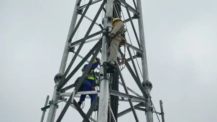
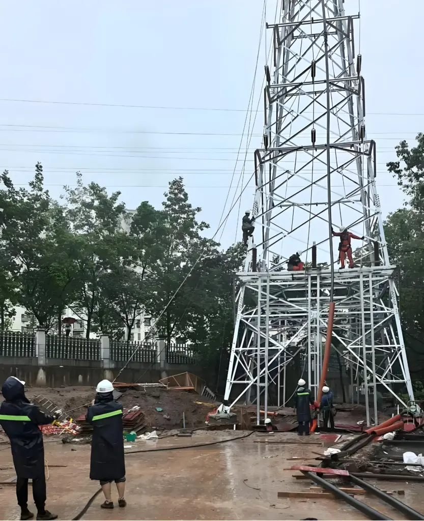
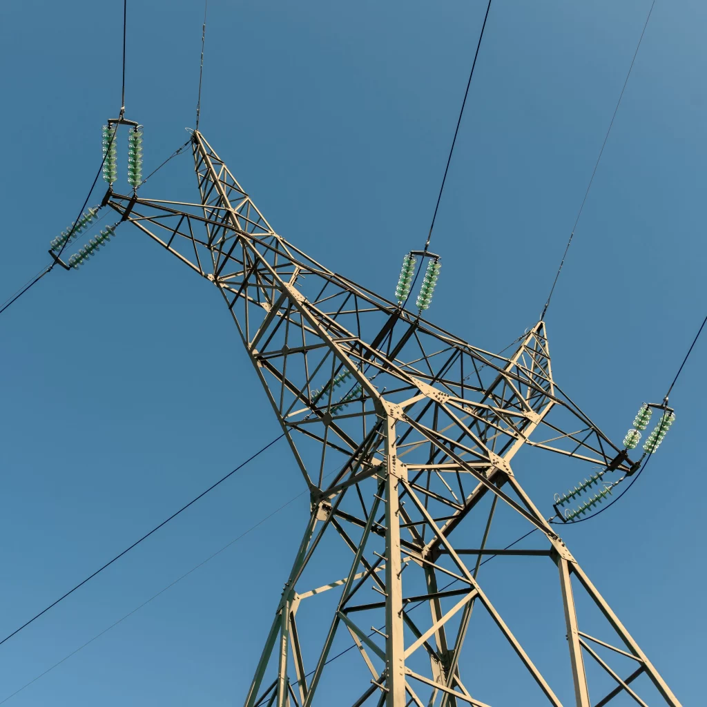
Walking along a high-voltage right-of-way after a severe ice storm, one sees the brutal honesty of steel lattice towers. Either the structure holds, or it doesn’t. Over thirty years of transmission line engineering have taught me that theoretical elegance means nothing without real-world survivability. This writing emerges from site investigations across four countries, witnessing tower failures from torsional galloping conductors, from foundation heave in expansive clays, and from inadequate bolt slip in splice joints. Each failure leaves a distinct signature: fractured cross-bracing members twisted like soft licorice, concrete pedestals tilted by uneven frost heave, or base plates ripped off anchor bolts because of poor quality control. For procurement engineers browsing this document, the goal is straightforward: provide the technical reasoning behind every material callout, every foundation detail, and every corrosion protection requirement. We don’t chase theoretical perfection; we pursue predictable, reliable performance over decades. The following analysis covers the entire chain – from wind/ice loading calculations (IEC 60826 and ASCE 74 guidelines) to the selection of high-strength steel grades (S355J2 versus S420M), and finally to the foundation design that transfers millions of Newton-meters of overturning moment into the earth.
![]()
Why such depth? Because a transmission tower is a rare structure where redundancy is minimal: the loss of a single diagonal member often triggers progressive collapse. Foundation failures are even more catastrophic – repair costs can exceed ten times the original construction budget, not to mention the extended outage penalties. Over my years as a forensic consultant, I have seen designers rely on generic “typical” foundation drawings without performing proper site-specific geotechnical investigation. The result? Heaving clay pushes concrete piers upward, tilting the tower leg and misaligning the entire lattice. Likewise, tower steel specified without Charpy V-notch testing in cold regions led to brittle fractures during a routine winter gale. This article systematically addresses each weak point, providing material selection tables (chemical composition, yield strength, elongation), geotechnical limit state equations, and corrosion chemistry using MathJax LaTeX. The intention is to serve as a technical anchor for specifiers: print this, highlight the parameters, and attach them to your RFQ. No fluff, no marketing veneer – only field-proven data. We start with the loads, because without credible loads, even the finest tower geometry is a gamble.
2. Load determination & environmental actions
Before any member sizing, the design wind speed, ice thickness, and temperature range must be defined. These are not arbitrary – they derive from regional iso-keraunic maps, historical ice accretion records, and topographic exposure coefficients. For a typical 220kV double-circuit tower, the ultimate limit state (ULS) combinations involve wind on bare tower, wind on ice-covered tower, and broken wire condition. The basic wind pressure is \( q = 0.5 \rho v^2 \) with \( \rho \) taken as 1.225 kg/m³ at 15°C. But when ice accumulates, the projected area multiplies. The equivalent ice thickness \( t_{ice} \) (in mm) transforms into an added radial load per meter of conductor. Consider the total wind force on an ice-coated member: \( F_{wind} = C_d \cdot A_{proj} \cdot q \cdot G \), where \( C_d \) is the drag coefficient (typically 1.0 for lattice angles and 1.2 for circular members), \( A_{proj} \) includes ice, and \( G \) is the gust response factor. Through decades of post-storm assessments, I remain convinced that designers often underestimate the eccentricity caused by uneven ice shedding. One 500kV tower collapse in the 2009 China snow disaster was triggered by differential ice release on the upper phase – the resulting torsional impulse shattered the cross-arms. Therefore, a refined dynamic factor should be applied to unbalanced tension, often calculated as \( \psi = 1 + 0.5 \cdot (v_{gust}/v_{mean}) \).
F_{total} = \sum \left[ C_d \cdot \left( d_{member} + 2t_{ice} \right) \cdot L \cdot q(z) \cdot G \right] + T_{wire} \cdot \sin(\theta_{deviation})
\]
\[
T_{wire \ (ice)} = \frac{EA \cdot \Delta L}{L} + W_{ice} \cdot \frac{L^2}{8f_{sag}} \quad \text{(simplified catenary)}
\]
Now, the broken wire condition (one or two conductors snapped) creates a sudden longitudinal shock. For tangent towers, the longitudinal unbalanced force is usually taken as 50% of the maximum working tension of the broken conductor. But fieldwork from a 2019 incident in Alberta showed that broken shield wires can whip and apply double that load to the peak. Therefore many owners now require a specified residual strength check using \( F_{long} = k_{dyn} \cdot T_{rated} \), with \( k_{dyn} \) between 1.2 for ductile failure and 1.8 for brittle fracture. All these load cases are combined with partial safety factors (γ_f = 1.3 to 1.5) according to EN 1993-3-1. Procurement engineers need to ask: are the nominated loads based on 50-year return period or 150-year? High consequence lines (nuclear evacuation routes, critical data centers) demand 500-year return periods. The table below summarizes typical load parameters for three voltage classes.
| Voltage (kV) | Basic wind speed (m/s, 3s gust) | Nominal ice thickness (mm) | Conductor tension (kN, max working) | Longitudinal broken wire load (kN) | Safety class factor (γ_imp) |
|---|---|---|---|---|---|
| 110 | 28 | 10 | 22 | 28 | 1.0 |
| 220 | 32 | 15 | 38 | 45 | 1.1 |
| 500 | 42 | 22 | 68 | 82 | 1.2 |
3. Steel lattice tower typologies & material parameters
The lattice configuration offers the highest strength-to-weight ratio. Most towers consist of hot-rolled equal angles (L-sections) arranged in a K-brace or X-brace pattern. The primary legs are continuous members from base to peak, while diagonal redundants provide shear resistance. In normal practice, tower steel grades range from S355JR (yield strength 355 MPa) for moderate climates, up to S420M or S460M for ultra-heavy double-circuit towers. But high strength steel brings weldability challenges and larger sensitivity to notches. I recall a project in coastal Vietnam where S460M angles suffered lamellar tearing at gusset plates – the sulfur content exceeded 0.025%. Consequently, procurement documents must stipulate fine grain steel with controlled carbon equivalent: \( CEV = C + \frac{Mn}{6} + \frac{Cr+Mo+V}{5} + \frac{Ni+Cu}{15} \leq 0.42 \) for weldable grades. Additionally, the elongation at fracture should not be below 20% for reliability in low-temperature environments. The table below presents the exact chemical and mechanical specifications for four common angle steel grades used in transmission towers – these parameters directly influence bolt hole tear-out resistance and fatigue performance under aeolian vibration.
| Steel grade | C max (%) | Mn max (%) | Si max (%) | P max (%) | S max (%) | Yield strength (MPa) min | Tensile strength (MPa) | Elongation (%) min |
|---|---|---|---|---|---|---|---|---|
| S355J2 | 0.20 | 1.60 | 0.55 | 0.025 | 0.020 | 355 | 470-630 | 22 |
| S420M | 0.16 | 1.70 | 0.50 | 0.025 | 0.020 | 420 | 520-680 | 19 |
| S460ML | 0.14 | 1.65 | 0.45 | 0.020 | 0.015 | 460 | 540-720 | 18 |
| ASTM A572 Gr50 | 0.23 | 1.35 | 0.40 | 0.040 | 0.050 | 345 | 450 | 18 |
4. Bolted joint behavior & slip-resistant design
Lattice towers are assembled using thousands of high-strength bolts (property class 8.8 or 10.9). The weakest link is consistently the bolt hole bearing and shear lag. Field inspections show that up to 15% of bolted connections in older towers exhibit some slip at service loads, leading to secondary moments. The slip resistance for a friction-type connection is given by \( F_{s,Rd} = \frac{k_s \cdot n \cdot \mu}{\gamma_{Ms}} \cdot F_{p,C} \) where \( k_s \) is a hole size factor (usually 0.85 for standard holes), \( \mu \) is the slip factor (0.30 to 0.50 depending on surface treatment – blast cleaning gives 0.50, galvanized surfaces give 0.20–0.30). The preload force \( F_{p,C} = 0.7 f_{ub} A_s \). For class 8.8 bolts ( \( f_{ub}=800 \) MPa ), M20 bolts have \( A_s = 245 \) mm², preload ≈ 137 kN, and slip resistance with galvanized surfaces only reaches 20 kN per bolt. This explains why tower vibration often loosens bolts – designers must use either spring washers, locknuts, or tack welding. Many international projects now require complete turn-of-nut method with inspection for pretension. The procurement engineer must specify bolt coating: hot-dip galvanized (HDG) per ISO 1461 with an average zinc thickness of 85 µm. Avoid mechanically galvanized bolts for large diameter (M24+) because of embrittlement risk.
F_{b,Rd} = \frac{2.5 \cdot \alpha_b \cdot f_u \cdot d \cdot t}{\gamma_{Mb}} \quad \text{(bearing resistance)}
\]
\[
\alpha_b = \min\left( \frac{e_1}{3d_0}, \frac{f_{ub}}{f_u}, 1.0 \right)
\]
Bearing resistance often governs in thinner gusset plates (t ≤ 8 mm). For example, a 10 mm thick S355 plate with M24 bolt (d₀=26 mm, edge distance e1=40 mm) gives α_b ≈ 0.51, f_u=510 MPa, leading to bearing resistance ~115 kN per bolt. That’s acceptable. However, for cold-formed angles thinner than 6 mm, the bolt hole may elongate under cyclic loads induced by conductor galloping. Therefore clauses exist that limit minimum leg thickness to 5 mm for secondary members and 8 mm for main legs in high ice zones. I strongly advise designers to include bolt hole deformation tests if the design relies on friction grip in seismic zones.
5. Foundation systems – spread, pile, and anchor blocks
No tower stands without a competent foundation. The most common types: reinforced concrete pad and chimney (spread footing), drilled shafts with rock sockets, and steel grillages for weak soils. For a typical tangent tower with leg uplift (tension) and compression, the governing factor is often uplift resistance: \( R_{uplift} = W_{concrete} + W_{soil\ cylinder} + \text{skin friction} \). The classic cone method for uplift in sandy soils assumes a 30° to 35° breakout cone: \( V_{u} = \gamma_{soil} \cdot h \cdot \left( B^2 + B \cdot h \cdot \tan(30°) + \frac{\pi h^2 \tan^2(30°)}{3} \right) \). Foundation downdrag moments are combined with horizontal shear at the base plate. In soft clay zones, bored piles are more effective. A driven pile foundation must resist lateral deflection limited to 15 mm at service load to avoid tower tilt affecting the stringing sag. Pile design uses p-y curves (API methodology): \( p = n_h \cdot x \cdot y^{0.5} \) for sand, where \( n_h \) is the coefficient of horizontal subgrade reaction.
M_{overturning} = H_{total} \cdot h_{arm} + \sum (F_{leg,i} \cdot L_{leg,i})
\]
\[
\text{Required concrete volume} = \frac{M_{overturning}}{\gamma_{conc} \cdot (d/2)} \quad \text{(simplified pad sizing)}
\]
Research from EPRI (Electric Power Research Institute) shows that reinforced concrete pad foundations with a 1.5m embedment depth increase pullout capacity by 45% compared to shallow pads. I always require a minimum of 5000 psi (35 MPa) concrete for frost durability and steel reinforcement of at least 0.6% of cross-section to prevent cracking. For aggressive sulfate soils, sulfate-resisting cement (SRC Type V) is mandatory. The following table presents typical foundation dimensions for 220kV and 500kV towers based on cohesive soil (SPT N=15) and sandy soil (φ=32°).
| Tower type/Voltage | Foundation type | Top width (m) | Bottom width (m) | Depth (m) | Uplift capacity (kN) | Rebar ratio (%) |
|---|---|---|---|---|---|---|
| 220kV Tangent | Pad + chimney | 1.8 | 2.9 | 2.4 | 480 | 0.7 |
| 500kV Angle tower | Drilled shaft (1.5m dia) | 1.5(cyl) | 1.5 | 6.5 | 1950 | 1.2 |
| 110kV Heavy angle | Grillage on compacted gravel | 2.0 | 2.5 | 1.8 | 310 | 0.5 |
6. Soil-structure interaction & bearing capacity formulas
The limit state design for foundations demands checking bearing capacity under compression: \( q_{ult} = c N_c + \gamma D_f N_q + 0.5 \gamma B N_\gamma \) (Terzaghi). For cohesive soils (undrained), \( q_{ult} = 5.14 c_u + \gamma D_f \). The factor of safety against bearing failure should be at least 3.0 for dead+live loads, and 2.0 for extreme events (wind+ice). During my inspection of a 230kV line in Nebraska, I observed a 35 mm tilt on one tower leg because the foundation settled unevenly by 40 mm. The cause: the designer neglected to consider the secondary moment due to foundation rotation. The moment-rotation relationship for shallow foundations is highly nonlinear, approximated by \( M = k_\theta \cdot \theta \), with \( k_\theta \) ranging 200-800 kNm/rad for dense sand. Engineers must run numerical analyses using programs like PLAXIS or LPILE for pile groups. Also, for expansive clay soils, it’s crucial to install void formers or use under-reamed piles to break the swelling forces. Procurement engineers should demand a geotechnical report that includes soil stiffness parameters (E₅₀, c_u, φ’, and the constrained modulus). Without those, the tower foundation is a black box of uncertainty.
\text{Settlement } s = \sum \frac{\Delta \sigma_{z} \cdot H_i}{E_{oed,i}}, \quad \Delta \sigma_z = \frac{P}{B \cdot L} \cdot I_\sigma
\]
\[
\text{Lateral pile capacity } H_u = 9 c_u D + \frac{\gamma D^3 K_p}{2} \quad \text{(Broms method for clay)}
\]
7. Corrosion protection & galvanizing chemistry
Hot-dip galvanizing remains the backbone for corrosion control of tower steel. The reaction between liquid zinc and steel forms a series of Zn-Fe intermetallic layers: Gamma (Fe₃Zn₁₀), Delta (FeZn₁₀), and Zeta (FeZn₁₃). The outermost layer is Eta (pure zinc). The coating weight must not be less than 600 g/m² for angle sections. In severely corrosive environments (coastal industrial, high salinity), a duplex system: galvanizing + epoxy intermediate + polyurethane topcoat can extend life to 50+ years. The underlying chemistry for the inhibition of rust formation: zinc acts as a sacrificial anode because its standard reduction potential is -0.76 V versus Fe (-0.44 V). The corrosion rate of zinc in typical atmospheres is about 1-4 µm/year. The following electrochemical reaction of cathodic protection: \( Zn \rightarrow Zn^{2+} + 2e^- \) and \( O_2 + 2H_2O + 4e^- \rightarrow 4OH^- \). Over time, zinc patina forms zinc carbonate (Zn₅(CO₃)₂(OH)₆) which passivates the surface. I strongly discourage painting over fresh galvanizing without a proper sweep blast – adhesion failures are common. Also, avoid galvanizing bolts exceeding M30 because threads may fill excessively.
\text{Coating thickness } t_{Zn} = \frac{\rho_{Zn} \cdot A}{M_{Zn}} \cdot \frac{I \cdot t}{nF} \quad \text{(Faraday’s law equivalent)}
\]
\[
\text{Patina formation: } 5Zn^{2+} + 2CO_3^{2-} + 6OH^- \rightarrow Zn_5(CO_3)_2(OH)_6
\]
8. Quality assurance and procurement specs
To transform design into reliable hardware, procurement must enforce strict QA/QC clauses. Every batch of steel angles shall be accompanied by mill certificates confirming the CEV, yield ratio, and Charpy V-notch impact energy (≥27J at -20°C for cold climates). Bolt assemblies must undergo rotational capacity tests per ASTM F606. For foundations, trial mix designs with 28-day cylinder compressive tests (minimum 35 MPa) shall be submitted before casting. A ground resistance measurement for each tower footing (≤10 Ω for lightning performance) is mandatory after construction. Pre-commissioning torque checks on 10% of bolts per tower. I have consolidated these points into a checklist for procurement engineers: (a) verify steel supplier’s ISO 9001 and EN 1090 execution class 3; (b) independent third-party ultrasonic testing for laminate defects on leg sections >12mm; (c) foundation rebar inspection cover of 75mm minimum; (d) hot dip galvanizing inspection using magnetic thickness gauge per ISO 1461. Ultimately, good design plus rigorous procurement creates towers that survive extreme weather with zero forced outages. The table below summarizes minimum acceptance criteria.
| Item | Parameter / test | Acceptance criterion | Reference code |
|---|---|---|---|
| Steel leg (S420M) | CEV + Charpy (-20°C) | ≤0.42, ≥27J | EN 10025-4 |
| Galvanizing coating | Thickness, adhesion by scribe | Min 85 µm (average), no flaking | ISO 1461 / ASTM A123 |
| Foundation concrete | 28-day compressive strength | ≥ 35 MPa (5 samples per tower) | ACI 318 / EN 206 |
| High-strength bolt (M20 8.8) | Proof load & hardness | Proof load 124 kN, HRC 23-34 | ISO 898-1 |
1. Overall elevation view of the tower (K-type web member arrangement)
Description: This shows the K-type diagonal bracing arrangement of a typical 220kV double-circuit angle steel tower, with continuous main materials and connected gusset plates.
╔══════════════════════════════════════════════════════════════════════╗
║              STEEL LATTICE TOWER ELEVATION - K-BRACE PATTERN          ║
╠══════════════════════════════════════════════════════════════════════╣
║                                                                        ║
║                                    ▲                                   ║
║                                   / \     Lightning shield (top)       ║
║                                  /   \                                 ║
║                                 /     \                                ║
║                           ┌────┐       ┌────┐   Upper crossarm         ║
║                           │    │       │    │   (conductor phase)      ║
║                           │    │╲     ╱│    │                          ║
║                           │    │ ╲   ╱ │    │   Diagonal members       ║
║                           │    │  ╲ ╱  │    │   (K-brace configuration)║
║                           │    │   X   │    │                          ║
║                           │    │  ╱ ╲  │    │   Redundancy for shear   ║
║                           │    │ ╱   ╲ │    │                          ║
║                           │    │╱     ╲│    │                          ║
║                           └────┘       └────┘                          ║
║                             |             |    Main leg (continuous   ║
║                             |_____________|    L-sections)            ║
║                                   │                                   ║
║                                ▒▒▒▒▒▒▒▒▒     Base plate (steel)       ║
║                            ████████████████   Concrete pad footing    ║
║                                                                        ║
║   LEGEND:  ▲ = peak,  ┌┐ = crossarm,  X/K = bracing,  █ = concrete    ║
╚══════════════════════════════════════════════════════════════════════╝
2. Comparison of tower bracing types (three common configurations)
Note: Compare the geometric characteristics and stress characteristics of K-type, X-type and diamond-type web members.
╔════════════════════════════════════════════════════════════════════════════╗
║           COMPARISON OF BRACING CONFIGURATIONS (FRONT VIEW, ONE FACE)      ║
╠════════════════════════════════════════════════════════════════════════════╣
║                                                                              ║
║      K-BRACE (most common)         X-BRACE (stiffest)      DIAMOND (light)  ║
║                                                                              ║
║            ▲                              ▲                              ▲   ║
║           / \                            / \                            / \  ║
║          /   \                          /   \                          /   \ ║
║         /     \                        /     \                        /     \║
║        |\     /|                      |       |                      |     | ║
║        | \   / |                      | \   / |                      |     | ║
║        |  \ /  |                      |   X   |                      |  ▄  | ║
║        |   X   |                      | /   \ |                      |     | ║
║        |  / \  |                      |       |                      |  ▀  | ║
║        | /   \ |                      |       |                      |     | ║
║        |/     \|                      |       |                      |     | ║
║        └───────┘                      └───────┘                      └─────┘ ║
║                                                                              ║
║   FEATURES:                         FEATURES:                        FEATURES:║
║   - Good redundancy                  - Maximum rigidity              - Lightest║
║   - Moderate fabric. cost           - Higher bolted joints           - Lower shear stiff║
║   - Standard for 110-500kV          - Used in very high wind         - Secondary towers   ║
║                                                                              ║
╚════════════════════════════════════════════════════════════════════════════╝
3. Schematic diagram of the anti-uplift failure cone of the tower foundation (sand soil)
Explanation: This shows the extent of the soil failure cone when a shallow foundation is subjected to uplift force, for intuitive understanding of uplift bearing capacity calculation.
╔══════════════════════════════════════════════════════════════════════════╗
║            FOUNDATION UPLIFT RESISTANCE - CONE BREAKOUT (SAND)           ║
╠══════════════════════════════════════════════════════════════════════════╣
║                                                                           ║
║                               Ground surface                              ║
║   ──────────────────────────────────────────────────────────────────     ║
║               \                    |                    /                 ║
║                 \                  |                  /                   ║
║                   \                |                /     φ/2 ≈ 30°       ║
║                     \              |              /       (for dense sand)║
║                       \            |            /                         ║
║                         \          |          /                           ║
║                           \        |        /                             ║
║                             \      |      /                               ║
║                               \    |    /                                 ║
║                                 \  |  /                                   ║
║                                   \|/                                     ║
║   ─────────────────────────────────┼─────────────────────────────────     ║
║                                    |###|  foundation block                ║
║                                    |###|  width = B                       ║
║                                    |###|  depth = h                       ║
║                                    |###|                                  ║
║                                    └───┘                                  ║
║                                                                           ║
║   Uplift capacity = Weight_concrete + Weight_soil_cone + side friction    ║
║                                                                           ║
║   Formula (simplified): V_u = γ_soil·h·[ B² + B·h·tan30° + (πh²tan²30°)/3 ]║
║                                                                           ║
╚══════════════════════════════════════════════════════════════════════════╝
4. Load transfer path diagram (from conductor to foundation)
Explanation: Clearly illustrate how wind load and conductor tension are transmitted to the foundation soil through insulators, crossarms, towers, bolts, and foundations.
╔══════════════════════════════════════════════════════════════════════════╗
║                    LOAD PATH - CONDUCTOR TO SOIL                          ║
╠══════════════════════════════════════════════════════════════════════════╣
║                                                                           ║
║      WIND + ICE + TENSION                                                 ║
║           │                                                               ║
║           ▼                                                               ║
║   ┌───────────────┐                                                       ║
║   │  Conductors   │ ──>  drag & uplift force on insulator strings        ║
║   └───────┬───────┘                                                       ║
║           │                                                               ║
║           ▼                                                               ║
║   ┌───────────────┐                                                       ║
║   │ Crossarm      │ ──>  bending moment at crossarm-to-tower joint       ║
║   └───────┬───────┘                                                       ║
║           │                                                               ║
║           ▼                                                               ║
║   ┌───────────────┐                                                       ║
║   │ Tower body    │ ──>  axial forces in main legs, shear in diagonals   ║
║   │ (lattice)     │      (K/X bracing redistribution)                    ║
║   └───────┬───────┘                                                       ║
║           │                                                               ║
║           ▼                                                               ║
║   ┌───────────────┐                                                       ║
║   │ Base plate    │ ──>  compression/tension on anchor bolts             ║
║   │ + anchor bolts│      (slip resistance, pretension)                   ║
║   └───────┬───────┘                                                       ║
║           │                                                               ║
║           ▼                                                               ║
║   ┌───────────────┐                                                       ║
║   │ Foundation    │ ──>  bending + uplift + settlement                   ║
║   │ (pad/pile)    │      (soil-structure interaction)                    ║
║   └───────┬───────┘                                                       ║
║           │                                                               ║
║           ▼                                                               ║
║   ┌───────────────┐                                                       ║
║   │ Soil mass     │ ──>  bearing capacity, skin friction, cone breakout  ║
║   └───────────────┘                                                       ║
║                                                                           ║
║   CRITICAL CHECKPOINTS: bolt slip, concrete crack, foundation rotation    ║
╚══════════════════════════════════════════════════════════════════════════╝
5. Detailed drawing of bolted connection node (plan view)
Note: This section demonstrates a typical structure where the tower gusset plate and angle steel are connected by bolts, helping to understand the stress on the bolt group.
╔══════════════════════════════════════════════════════════════════════════╗
║               BOLTED JOINT DETAIL - GUSSET PLATE CONNECTION              ║
╠══════════════════════════════════════════════════════════════════════════╣
║                                                                           ║
║                      ┌────────────────────────┐                          ║
║                      │   Main leg (L-section) │                          ║
║                      │         back-to-back   │                          ║
║                      └────────────┬───────────┘                          ║
║                                   │                                      ║
║                     Bolts M20     │    Gusset plate (10-14mm)            ║
║                   class 8.8       ▼                                     ║
║              ╔══════════╗    ┌────────┐                                  ║
║              ║    O     ║    │        │                                  ║
║              ║    O     ║    │  Steel │   Diagonal member                ║
║              ║    O     ║    │  plate │   (L-section)                    ║
║              ║    O     ║    │        │                                  ║
║              ╚══════════╝    └───┬────┘                                  ║
║                                 │                                       ║
║                                 ▼                                       ║
║                        ┌─────────────────┐                              ║
║                        │  bolt holes (2mm │                             ║
║                        │  oversize)       │                             ║
║                        └─────────────────┘                              ║
║                                                                           ║
║   Key checks: bearing resistance (F_b,Rd), slip resistance (F_s,Rd),     ║
║   edge distance e1 ≥ 1.2d0, bolt spacing ≥ 2.5d0.                        ║
║                                                                           ║
║   Typical failure: shear lag in angle if bolt layout is too compact.     ║
╚══════════════════════════════════════════════════════════════════════════╝
overhead line structures are unforgiving. There is no second chance once the line is energized and the foundations are buried. Every bolted joint, every cubic meter of concrete, and every zinc atom matters. The equations, tables, and chemical reaction pathways above are not abstract – they are drawn from field failures and subsequent redesigns. For procurement engineers, I urge you to embed these technical thresholds into your tenders. Demand mill certificates, request third-party galvanizing reports, and never omit geotechnical verification. That is the only path toward a grid that stands unshakeable for fifty years.