
Visual Analysis for Determining Transmission Line Voltage
Overhead Transmission Line Towers Technical Analysis
November 29, 2025Technical Analysis of 110kV to 750kV Transmission Line Towers
December 7, 2025The Deciphering of Power: Visual Analysis and Technical Deduction for Determining Transmission Line Voltage
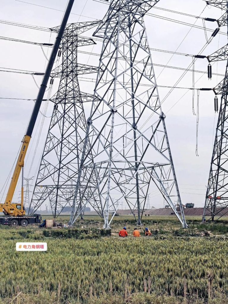
The colossal steel lattice towers that stride across the landscape, carrying the lifeblood of the modern electrical grid, are not merely arbitrary structural forms; they are crystallized solutions to highly constrained problems dictated by the fundamental laws of electrical physics, insulation coordination, and structural mechanics. The geometric profile of an overhead transmission tower—its height, the spread of its cross-arms, the length of its insulating strings, and the configuration of its conductors—is an open technical dossier that, when properly interpreted, reveals the precise operational voltage of the line it supports. Determining the voltage level solely by external appearance is a profound exercise in applied deductive engineering, requiring the observer to translate visual scale and component density into the underlying electrical parameters of the system. This analytical process is driven by the fact that the two dominant factors—the required electrical clearance and the necessity for insulation coordination—scale non-linearly with the system voltage, forcing commensurately dramatic and highly visible changes in the tower’s physical architecture.
1. The Principle of Electrical Clearance: Insulation and Leakage Distance
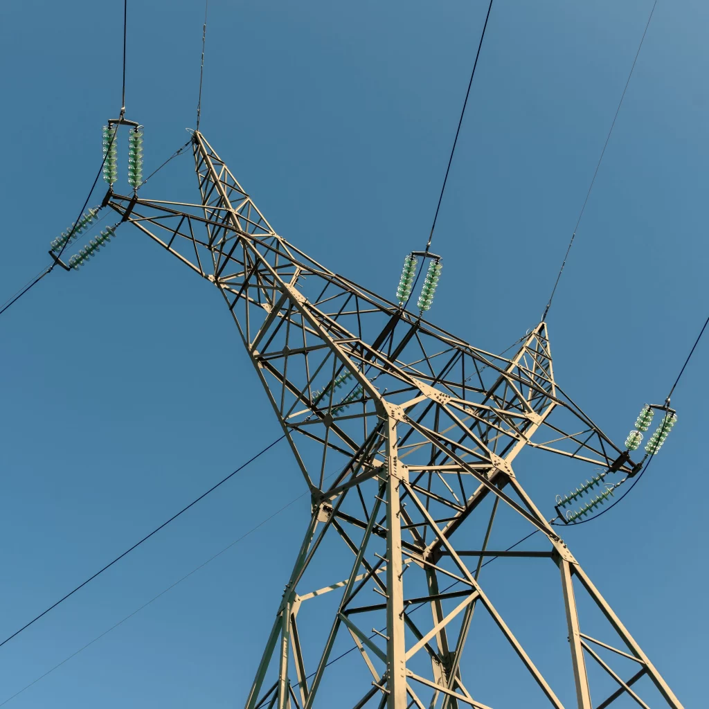
The most immediate and quantitatively reliable visual indicator of a line’s operational voltage is the length of the insulator assembly. The primary function of the insulator, whether composed of ceramic porcelain discs, toughened glass bells, or modern composite polymer rods, is to physically and dielectrically separate the energized conductors from the grounded potential of the steel tower structure. The required length of this separation is directly proportional to the maximum anticipated voltage stress across the insulating medium (air and the insulator body) under normal operating, lightning surge, and switching surge conditions.
The Visual Calculus of Insulation Coordination
The required length of the insulator string is determined by the necessity to withstand the Basic Impulse Insulation Level (BIL) and the Switching Impulse Level (SIL). The BIL relates to the short-duration, high-magnitude voltage surges caused by lightning strikes, while the SIL relates to the longer-duration surges induced by switching operations within the substation. For any given voltage class, engineering standards (such as those established by IEC, ANSI, or national regulatory bodies) specify a minimum number of standard insulator discs or a minimum length of the polymer equivalent required to prevent flashover—the unintended electrical arc across the insulation surface or through the surrounding air to the grounded tower structure.
For instance, an observer can deduce a rough voltage classification by counting the visible porcelain or glass discs on the insulator string. While regional standards vary, a general rule of visual thumb exists:
-
Low Voltage (LV) and Medium Voltage (MV) Distribution Lines (e.g., $10 \text{ kV}$ to $35 \text{ kV}$): Often require only two to five standard discs, or a very short polymer rod, typically installed on distribution poles or simple cross-arms.
-
High Voltage (HV) Transmission Lines (e.g., $110 \text{ kV}$ to $161 \text{ kV}$): Typically require a string of six to ten discs. The string length becomes noticeably substantial, visibly drooping under the weight of the conductor.
-
Extra-High Voltage (EHV) Lines (e.g., $345 \text{ kV}$ to $500 \text{ kV}$): Require long, visually impressive strings, often twelve to twenty discs or more. At this level, the strings may be doubled or even tripled in parallel (V-strings or tension strings) to handle the extreme electrical and mechanical forces, creating a visually complex, elongated structure.
-
Ultra-High Voltage (UHV) Lines (e.g., $750 \text{ kV}$ and above): The strings become colossal, sometimes exceeding twenty-five discs, and the assemblies are often arrayed in V-shapes (V-strings) attached to massive cross-arms, a geometric necessity to prevent the immense conductor sway from violating the minimum approach distance to the tower body.
The visible length of the insulator string is a direct physical manifestation of the required Creepage Distance—the minimum distance required along the surface of the insulator to prevent tracking and leakage currents, which is crucial in polluted, coastal, or humid environments. As voltage increases, the required creepage distance also increases, necessitating longer strings or specialized anti-fog insulator designs with deeper, more complex skirts, visually distinguishing them from standard designs. The visual confirmation of extreme insulator length is thus the electrical engineer’s first and most reliable clue regarding the line’s voltage classification, a clue founded in the physics of dielectric breakdown and impulse coordination.
2. Geometric Scaling: Phase Spacing, Cross-Arms, and Tower Profile
Beyond the insulator itself, the second crucial visual indicator is the scale and geometry of the tower’s conductive volume, defined by the minimum air gap required between energized components and between phases. As the operational voltage rises, the dielectric strength of the air becomes the limiting factor, necessitating increasingly large spatial separation to prevent arcing and maintain line reliability. This scaling is what fundamentally dictates the tower’s overall structural silhouette.
Minimum Approach Distance (MAD) and Cross-Arm Length
The required Minimum Approach Distance (MAD)—the shortest distance between any energized conductor and any grounded part of the tower (cross-arms, body, braces)—increases substantially with voltage. This requirement translates directly into the length of the tower’s cross-arms.
-
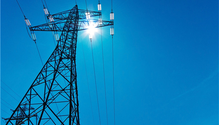
Low Voltage Compactness: A $138 \text{ kV}$ tower can afford relatively short cross-arms because the MAD is minimal, allowing for a geometrically compact and visually dense structure. The phases are relatively close together, often stacked vertically (vertical configuration) or in a tight delta pattern.
-
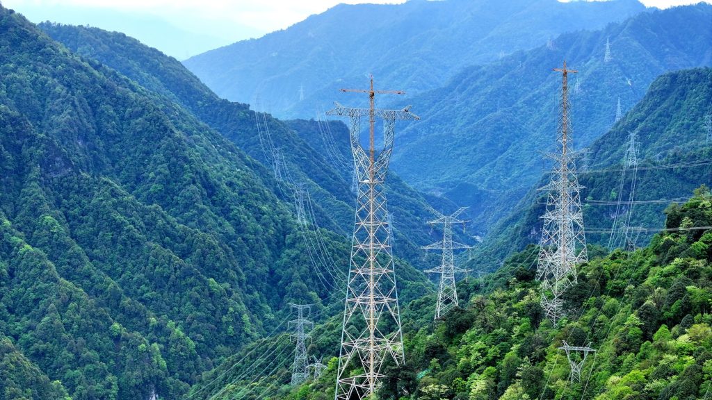
EHV/UHV Expansion: A $500 \text{ kV}$ or $750 \text{ kV}$ tower demands dramatically longer cross-arms. The required air clearance forces the conductors to be spread wide apart both horizontally (inter-phase spacing) and vertically (ground clearance and vertical phase spacing). This leads to a visually massive, open architecture with long, tapering cross-arms that appear to hold the conductors far away from the grounded steel body. The width of a $750 \text{ kV}$ tower base and its cross-arms can be several times that of a $220 \text{ kV}$ tower, a purely geometric response to the voltage-induced electrical clearance constraint.
Furthermore, the electrical stress between phases (inter-phase spacing) also increases, requiring greater separation to prevent phase-to-phase faults, particularly during high conductor sway events. The visual evidence of this is the sheer horizontal span the cross-arms must cover, often leading to distinct tower profiles:
-
Double-Circuit Towers: At lower voltages (up to $220 \text{ kV}$), double-circuit towers are common, where two sets of three phases are mounted on the same structure. The geometry is visually complex but relatively compact vertically. At UHV levels, double-circuit configurations are rare or require truly gargantuan towers due to the immense required inter-circuit and inter-phase clearances, often making two single-circuit towers the more practical, though visually broader, solution.
-
V-String Configuration: The massive cross-arms on EHV/UHV lines are frequently needed to accommodate V-string insulators. These V-shaped assemblies are utilized to restrict the lateral swing of the long insulator strings, ensuring that the conductor remains within the required MAD envelope even under high wind loading. The presence of these wide, rigid V-strings is a definitive visual signature of a high-voltage environment (typically $345 \text{ kV}$ and above), betraying the engineering necessity to control conductor movement precisely.
The visual process is one of deduction: the wider the horizontal and vertical separation of the conductors relative to the overall tower height, the higher the operational voltage must be, as the clearance requirements are the only fundamental drivers that mandate this massive increase in structural footprint.
3. The Physics of Conductor Management: Corona, Bundling, and Mechanical Load
The increase in voltage fundamentally changes not only the insulation requirements but also the physics governing the conductors themselves, leading to visible modifications in the wire configuration that are distinct indicators of EHV/UHV transmission.
Corona Discharge and Conductor Bundling
When high voltage is applied to a single conductor, the electric field strength at the conductor’s surface can exceed the dielectric strength of the adjacent air, leading to corona discharge—a visually discernible glow, an audible crackling sound, and, most importantly, a significant loss of electrical energy. To mitigate this effect, EHV and UHV lines do not use single conductors; instead, they employ bundled conductors.
-
Visual Identification of Bundling: The presence of multiple sub-conductors grouped together (typically two, three, four, or even six per phase) is a non-negotiable visual proxy for high voltage. The observer can directly count the sub-conductors per phase, and the number provides a tight correlation with the voltage class:
-
$220 \text{ kV}$ to $345 \text{ kV}$: Often utilize twin (two) sub-conductors per phase.
-
$500 \text{ kV}$: Often utilize triple (three) or quad (four) sub-conductors per phase.
- $750 \text{ kV}$ to $1,000 \text{ kV}$ (UHV): Often utilize quad or six-conductor bundles, held in precise geometric formation by spacers visible along the span.The sheer, palpable thickness of the overall bundle, held together by these metallic spacers, is an instantaneous visual giveaway that the line is operating at a very high electrical potential, where control of the surface electric field is paramount to efficiency and reliability.
-
Structural Scaling Due to Mechanical Load and Sag
The necessity for taller, wider towers is also a function of mechanical engineering principles linked back to the electrical requirements. Higher voltage lines are designed to carry significantly more power, which means the conductors are larger (to manage ampacity and thermal limits) and often bundled. The resulting line is inherently heavier, increasing the tension and the total vertical load that must be supported by the tower structure.
-
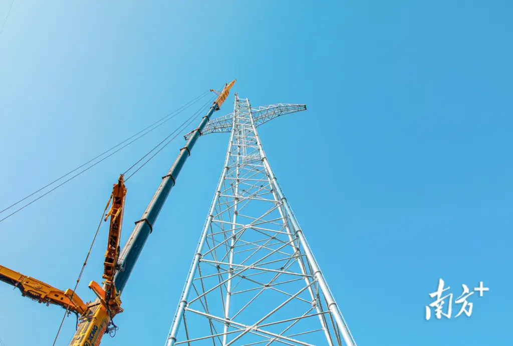
Tower Height for Ground Clearance: Operating at higher voltages introduces the potential for greater fault current magnitudes, requiring stricter regulations regarding the Minimum Ground Clearance in case of fault-induced line sag (thermal expansion or dynamic swing). Furthermore, the required electrical isolation means conductors must be physically higher above the terrain. This dictates a visibly taller tower, often transitioning from the $30 \text{ meter}$ range for lower voltages to well over $60 \text{ meters}$ for UHV lines, with significantly wider and heavier foundations to resist the overturning moment.
-
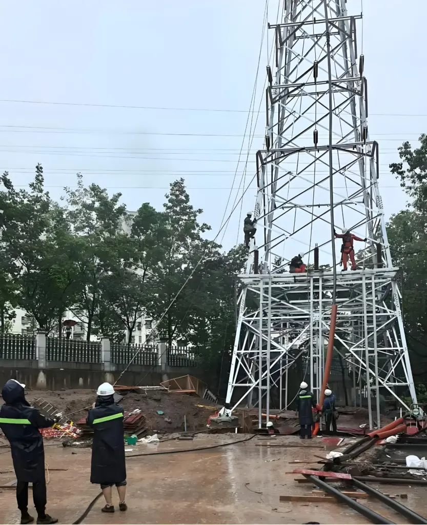
Bracing Complexity: The visual complexity of the lattice steel bracing in the tower body (the web members) also increases with voltage. The larger conductors and longer spans translate to higher mechanical tension and shear forces acting on the tower structure. To handle these amplified forces, the tower requires more robust cross-members, heavier gauge steel sections, and complex K-bracing or X-bracing patterns that visually reinforce the structure’s ability to resist buckling and shear failure, signaling its deployment in a high-load, high-tension (and thus high-voltage) environment. The visual shift from a slender, simple structure to a massive, architecturally complex truss is the structural engineer’s tacit confirmation of the enormous electrical loads being transported.
4. Integrated Visual Cues, Structural Typology, and Conclusion
The skilled observer integrates all these discrete visual data points—insulator length, phase spacing, and bundling—into a coherent analysis of the line’s voltage class, often cross-referencing these features with the overall structural typology.
The Visual Signature of Voltage Classes
The process of visual voltage determination is holistic:
-
Sub-Transmission ($69 \text{ kV}$ to $161 \text{ kV}$): Visual signature is a relatively dense structure with shorter cross-arms, often utilizing simple suspension insulators (six to ten discs), and predominantly single conductors per phase.
-
High-End EHV ($345 \text{ kV}$ to $500 \text{ kV}$): Visual signature is a wide-span, taller structure with long cross-arms and V-string insulators (twelve to twenty discs). The conductors are visibly bundled, typically dual or quad. The geometry is driven by electrical clearance, making the tower appear more “open” and less dense than lower-voltage counterparts.
-
UHV ($750 \text{ kV}$ and above): Visual signature is overwhelming height and width, often featuring colossal cross-arms to accommodate quad or six-conductor bundles. The insulator strings are immense, and the structural complexity of the steel lattice is maximized to handle the massive mechanical loads and clearances. The sheer scale is incomparable to any other voltage class.
Other subtle visual cues confirm this analysis: the presence of specialized dampers (e.g., Stockbridge dampers or armor rods) on the conductors is more common on high-tension, high-voltage lines to counteract wind-induced vibration and fatigue; the diameter of the overall bundled conductor is significantly larger than lower voltage lines, even if the sub-conductors are individually comparable.
The visual determination of a transmission line’s voltage level is thus a rigorous exercise in applied physics and engineering forensics. It requires the observer to deduce the invisible electrical parameters—impulse voltage, dielectric breakdown, and surface electric field—from the visible, tangible architecture of the tower. The structure’s immense size, its geometrically enforced separation distances, and the complex bundling of its conductors are all direct, non-negotiable consequences of the attempt to contain and transport vast electrical power efficiently and reliably. The tower stands, therefore, as a physical, metallic testament to the magnitude of the electrical forces it has been engineered to master.