
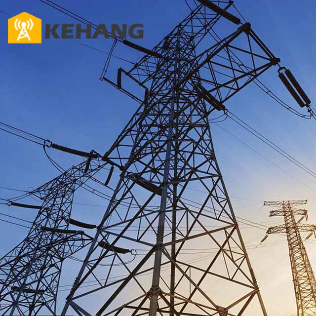
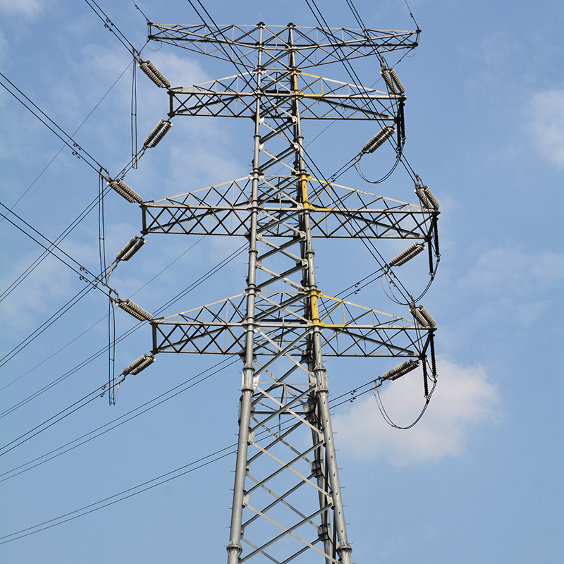
330kV Electric Transmission Line Tower
Wind Load Resistance in Self-Supporting Lattice Transmission Towers
December 27, 2025
Key Factors Affecting Life Cycle Cost (LCC) of Telecom Towers: Structural & Environmental Hierarchy
January 5, 2026Engineering the Backbone of the Grid: The 330kV Electric Transmission Line Tower
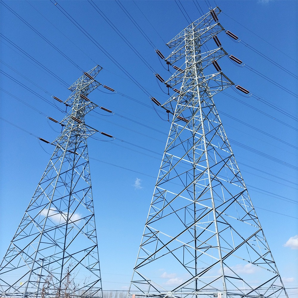
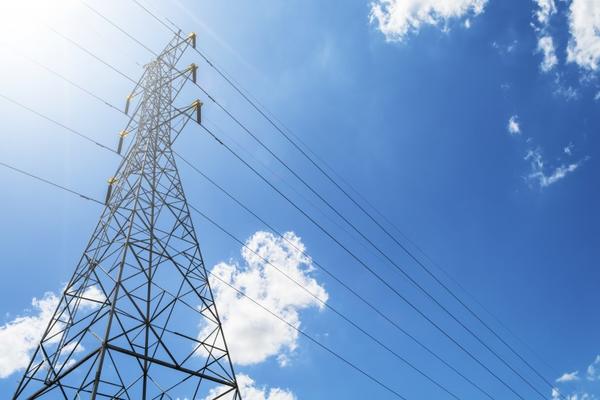
When we contemplate the structural anatomy of a 330kV Electric Transmission Line Tower, we are moving beyond simple civil engineering into a realm of high-stakes atmospheric physics and advanced material science. These structures are not merely static steel frames; they are the high-capacity conduits of modern civilization, designed to withstand the violent interplay between extreme electrical gradients and unpredictable meteorological forces. At the 330kV level, we are operating in the Extra High Voltage (EHV) domain, where the margin for error in insulation distance, structural vibration, and metallurgical fatigue is virtually nonexistent. To understand this product is to understand the sophisticated balance between the Newtonian mechanics of a massive vertical cantilever and the Maxwellian electrodynamics of high-frequency power surges.
The Physics of Structural Integrity and Material Selection
The primary challenge in 330kV tower design is the management of the Overturning Moment. Standing often between 30 and 55 meters, these towers act as immense levers against the wind. Our engineering process begins with the selection of high-grade, low-alloy structural steels, typically Q355B or Q420. We don’t just look at tensile strength; we look at the yield-to-tensile ratio to ensure that under extreme “Limit State” loading—such as a catastrophic ice storm or a sudden microburst—the tower exhibits ductile behavior rather than brittle failure. The lattice geometry is optimized using Finite Element Analysis (FEA) to ensure that the slenderness ratio of every diagonal bracing member prevents Euler buckling. We meticulously calculate the Drag Coefficient ($C_{d}$) of the angle steel, ensuring that the lattice “breathes” with the wind rather than fighting it, which significantly reduces the pressure exerted on the foundation stubs.
| Technical Parameter | Specification & Standard |
| Nominal System Voltage | 330kV |
| Maximum System Voltage | 362kV |
| Material Standards | ASTM A36, A572, or GB/T 1591 (Q235/Q355/Q420) |
| Anti-Corrosion | Hot-Dip Galvanization (ISO 1461 / ASTM A123) |
| Design Wind Speed | Up to 45 m/s (Adjustable per regional topography) |
| Ice Thickness Design | 0mm – 20mm (Heavy-ice area specialization available) |
| Insulator Configuration | I-string, V-string, or Tension Assemblies |
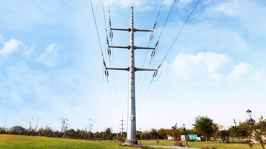
Electromechanical Coordination and Corona Mitigation
In the 330kV range, the electrical environment is intense. The surface voltage gradient on the conductors is high enough to ionize the surrounding air, leading to Corona Discharge. Our tower cross-arm designs are specifically calibrated to maintain “Clearance Windows” that account for both static and dynamic conditions. We must anticipate the Swing Angle of the insulator strings under heavy crosswinds; as the conductors move toward the tower body, the air gap decreases. Our technical analysis ensures that even at the maximum swing, the “Minimum Gap” remains sufficient to prevent a power-frequency flashover. Furthermore, the vertical spacing between phases is calculated to prevent Mid-span Galoping—a phenomenon where ice-coated wires act like airfoils and oscillate violently, potentially causing phase-to-phase short circuits.
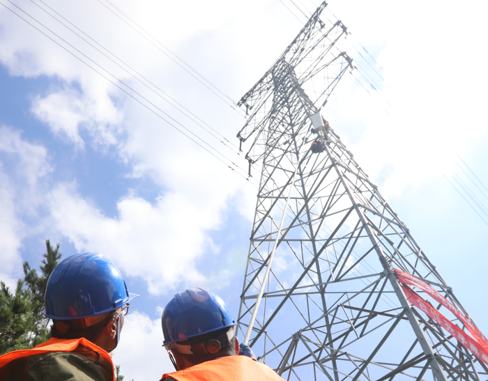
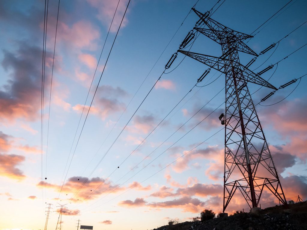
The shielding system is equally critical. The “Peak” of the tower serves as the mounting point for OPGW (Optical Ground Wire) or galvanized steel shield wires. We utilize the Electro-Geometric Model (EGM) to determine the optimal shielding angle (usually between 15° and 20°) to ensure that the live conductors are protected from direct lightning strikes. When a strike does occur on the shield wire, the tower must act as a massive grounding electrode. We focus heavily on the Tower Footing Resistance; by employing radial earthing or deep-driven grounding rods, we ensure that the surge impedance is low enough to prevent “Back Flashover,” where the lightning current jumps from the grounded tower back onto the live conductor because the ground path was too resistive.
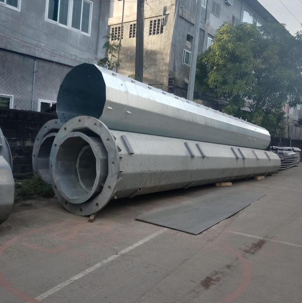
Advanced Manufacturing and Longevity
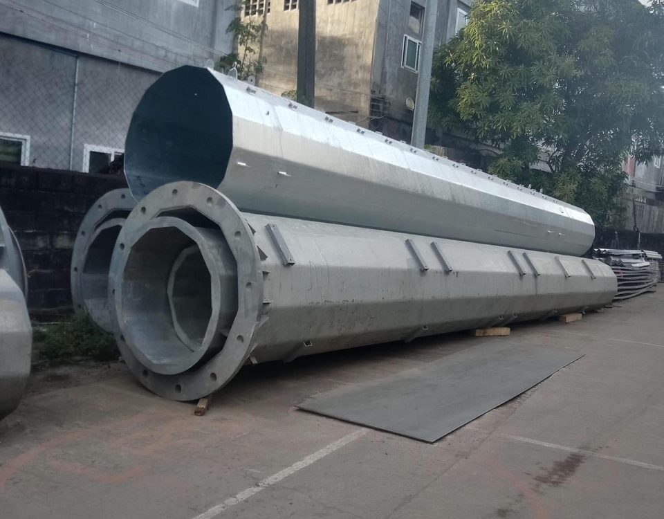
Durability is the hallmark of our 330kV towers. Every piece of steel undergoes a Hot-Dip Galvanization process that creates a series of zinc-iron alloy layers, providing decades of sacrificial protection against atmospheric corrosion. This is particularly vital in industrial or coastal environments where sulfur dioxide or salt spray can decimate unprotected steel in years. We monitor the Sandelin Effect during the galvanizing process, ensuring that the silicon content in our steel leads to a smooth, uniform, and non-brittle coating. On the assembly side, our CNC-controlled punching and drilling ensure that the pre-stressing of members during installation is minimized. A tower that is “pulled” into alignment during construction is a tower that carries internal stresses it wasn’t designed for; our precision ensures a “neutral” fit that preserves the full design capacity of the structure.
-
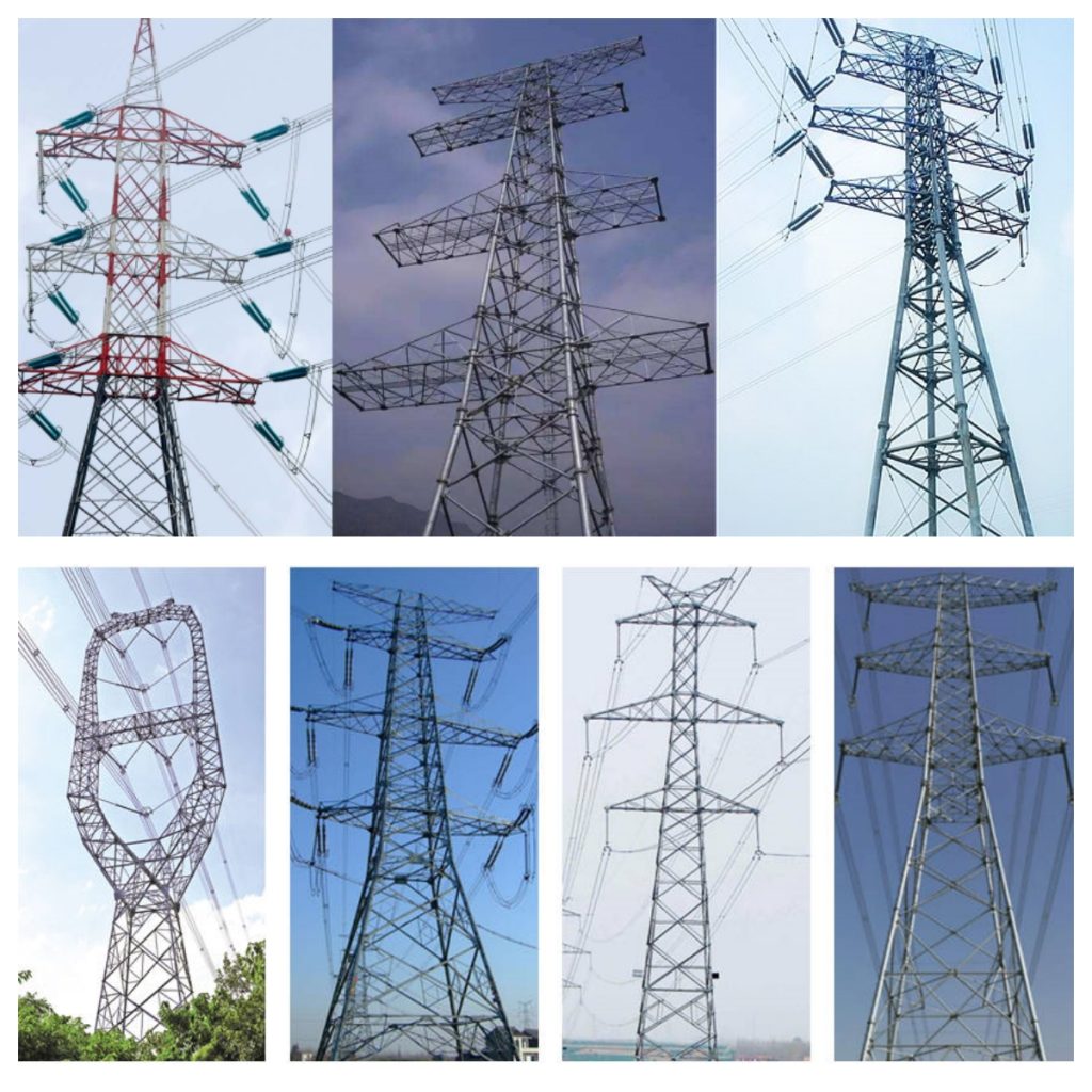
Customizable Geometry: Whether your terrain requires “Suspension,” “Tension/Angle,” or “Dead-end” towers, our designs are adapted for specific span lengths and line deviations.
-
Climate-Specific Resilience: We offer specialized low-temperature steel for Arctic conditions and enhanced structural reinforcement for hurricane-prone regions.
-
Ease of Installation: Standardized bolt sizes and clear marking systems reduce field errors and speed up the “Stringing” process, significantly lowering the Total Cost of Ownership (TCO).
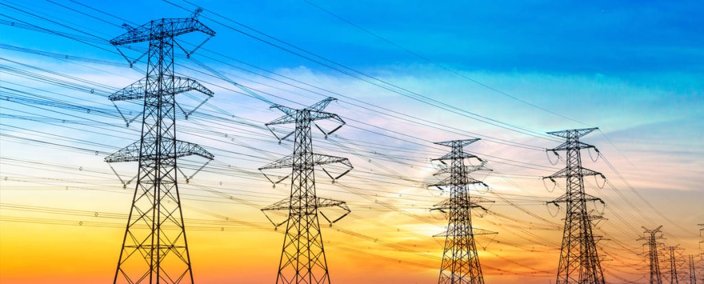
Our 330kV towers represent the pinnacle of reliability for regional grid interconnections. They are engineered for a 50-year service life, providing the stability required for modern energy markets and the integration of renewable energy sources.
When we sit down to conceptualize the structural integrity and electromechanical performance of a 330kV electric transmission line tower, we are not merely looking at a skeletal arrangement of galvanized steel; rather, we are engaging with a high-stakes architectural solution to the problem of atmospheric dielectric breakdown and the relentless pull of gravitational and environmental loads. The 330kV threshold is a fascinating intermediate point in the Extra High Voltage (EHV) spectrum, often serving as the backbone for regional interconnections where 500kV might be overkill but 220kV lacks the necessary power density to overcome the $I^{2}R$ losses inherent in long-distance bulk power transfer. To truly analyze this product, one must first obsess over the lattice geometry and how the selection of Q355B or Q420 high-strength steel dictates the slenderness ratios of the leg members. We begin by looking at the tower as a vertical cantilever beam, subjected to a complex cocktail of forces including the static weight of the ACSR (Aluminum Conductor Steel Reinforced) bundles, the dynamic oscillations induced by Karman vortex shedding, and the massive longitudinal pull-off forces that occur during a broken wire scenario.
The Structural Philosophy: Lattice Optimization and Wind Loading
The design of a 330kV tower starts with the fundamental choice of the “Waist” and “Cage” dimensions. In a typical self-supporting lattice configuration, the width of the tower base is mathematically tied to the overturning moment. If we go too narrow to save on the footprint or land acquisition costs, we increase the compressive and tensile stresses on the foundation stubs, necessitating massive concrete piers that might offset the steel savings. We must consider the Drag Coefficient ($C_{d}$) of the individual angle members. At 330kV, the tower height often ranges from 30 to 50 meters, placing the upper cross-arms directly in the path of higher-velocity laminar winds. We use the Power Law or Logarithmic Law to extrapolate wind speeds from the standard 10-meter reference height to the actual height of the conductor attachments. The turbulence intensity at these heights creates a fatigue cycle that most designers underestimate; every gust causes a microscopic deflection in the lattice joints, making the choice of M16 to M24 high-strength bolts and their subsequent torque specifications a matter of long-term structural survival rather than just simple assembly.
Moving deeper into the technical weeds, we have to address the “Bundle Effect.” At 330kV, we almost always see a twin-bundle conductor configuration. This isn’t just about current-carrying capacity; it’s about managing the surface voltage gradient. If the electric field strength at the surface of the conductor exceeds the “inception voltage” of the surrounding air, we get corona discharge—that characteristic buzzing sound that represents lost revenue and electromagnetic interference. The tower’s cross-arm must be designed with a “Window” large enough to maintain the minimum air gap (clearance) even when the insulator string swings 45 degrees or more due to crosswinds. This is where the P-Delta effect comes into play; as the tower leans slightly under wind pressure, the vertical weight of the conductors creates an additional eccentric moment that the structural analysis software must iterate until convergence. We are essentially designing a structure that must remain elastic under 50-year return period storms while anticipating the inelastic “buckling” behavior of the diagonal bracing if a “downburst” or “microburst” event exceeds the design limit.
Electrical Clearances and Insulator Dynamics
The electrical heart of the 330kV tower is the clearance diagram. We must account for three distinct conditions: the power frequency voltage (standard operation), the switching surge (internal transients), and the lightning impulse (external transients). For a 330kV system, the “Minimum Gap” is usually in the neighborhood of 2.2 to 2.8 meters depending on the altitude. However, we also have to think about the “Galoping” of conductors—those low-frequency, high-amplitude oscillations caused by asymmetric ice buildup on the wires. If the tower isn’t designed with sufficient vertical spacing between the phases (the “Phase-to-Phase” clearance), a gust of wind could cause a mid-span flashover, tripping the entire line. The insulators themselves, whether toughened glass or composite silicone rubber, act as the mechanical interface between the live wire and the grounded steel. The V-string or I-string configuration chosen for the tower affects the “Swing Angle.” A V-string holds the conductor more rigidly, allowing for narrower rights-of-way and smaller tower windows, but it doubles the insulator cost and increases the vertical load on the cross-arm tips.
The grounding system (Earthing) is the unsung hero of the 330kV tower. A tower is a giant lightning rod. When lightning strikes the overhead shield wire (OPGW or steel strand), the current rushes down the tower body. If the “Tower Footing Resistance” is too high—say, over 10 to 15 Ohms—the voltage at the top of the tower will rise so high that it “flashes back” to the conductor. This is a “Back Flashover.” To prevent this, we employ a sophisticated radial grounding array or deep-driven electrodes, ensuring that the surge impedance of the tower remains low enough to shunt kilo-amperes of current into the earth without destroying the insulator strings. We also have to consider the “Shielding Angle.” The placement of the earth wires at the very peak of the tower is calculated using the Electro-Geometric Model (EGM) to ensure that the conductors fall within the “shadow” of the shield wires, protecting them from direct lightning strikes.
Material Science and Environmental Resistance
From a metallurgical perspective, the 330kV tower is a masterclass in atmospheric corrosion resistance. Because these towers are expected to stand for 50 years in environments ranging from humid coastal plains to arid high-altitude deserts, the hot-dip galvanization process is critical. We aren’t just painting the steel; we are creating a metallurgical bond where the zinc-iron alloy layers provide sacrificial protection. The thickness of this coating, often measured in microns (typically 85μm to 100μm for these voltages), is dictated by the silicon content in the steel, which controls the “Sandelin Effect.” If the silicon content is in the “wrong” range, the zinc coating becomes brittle and grey, flaking off and leaving the structural steel vulnerable to rust. We also must consider the “Brittle Fracture” of the steel in sub-zero temperatures. In cold regions, we specify “Impact Tested” steel (e.g., Q355D or E) to ensure that the lattice doesn’t shatter like glass when hit by a sudden gust of wind on a -40°C night.
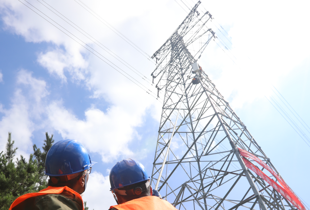
The manufacturing precision required for these towers is immense. Every hole for the bolts is punched or drilled with CNC accuracy because, in a lattice structure with thousands of members, a 2mm error in a gusset plate at the base will amplify into a 200mm lean at the peak. This “Pre-loading” or “Initial Imperfection” can drastically reduce the buckling strength of the main legs. When we simulate the “Load Cases,” we aren’t just looking at “Normal Weather.” We simulate “Heavy Ice,” “Broken Wire in Phase A,” “Torsional Loading from Uneven Ice,” and even “Construction Loading” where a lineman’s weight and the tensioning equipment create localized stresses that the tower was never meant to handle in its final state.