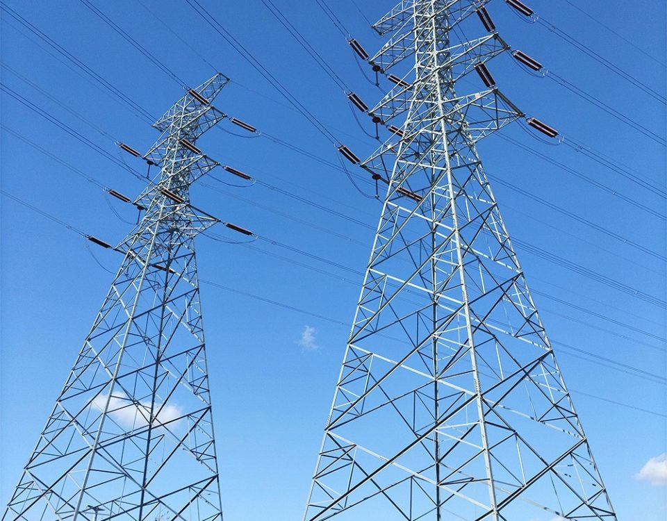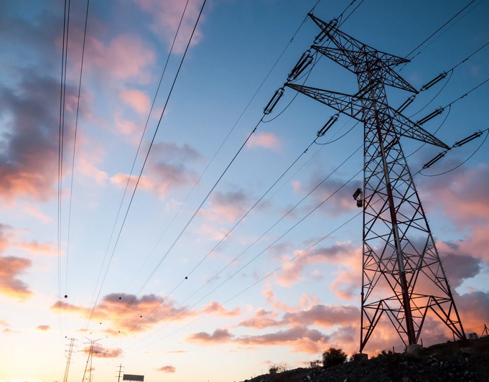
Hot Dip Galvanized Steel Lattice Power Transmission Tower

Monopole Telecommunication Antenna Tower | 25m HDG Steel Technical Specs & Engineering Analysis
May 16, 2026
Structural Lightning Protection Towers
August 16, 2026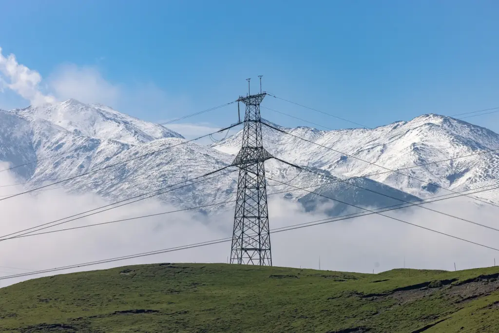
IEEE & IEC Certified Infrastructure
Hot Dip Galvanized Steel Lattice Power Transmission Tower
Heavy-duty high-voltage structural overhead line solutions engineered for global power grid systems from 11kV up to 1000kV. Maximum wind resistance, extreme anti-corrosion, and absolute mechanical longevity.
Premium Angle Steel Transmission Line Tower – Engineered for High-Voltage Networks
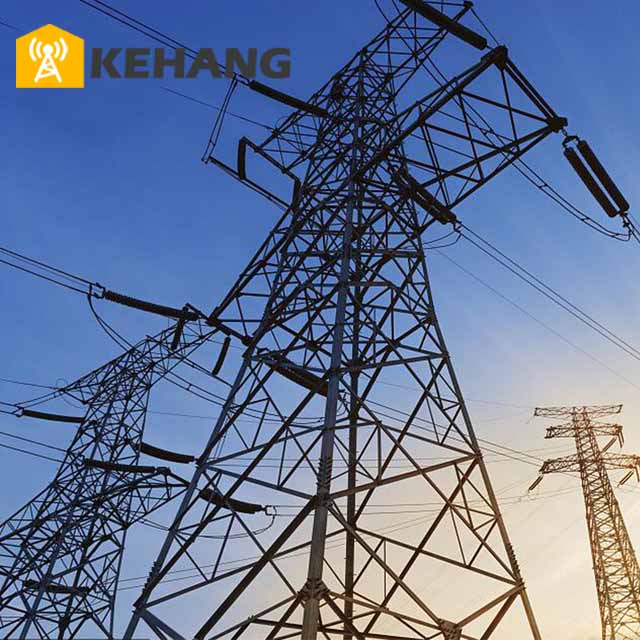
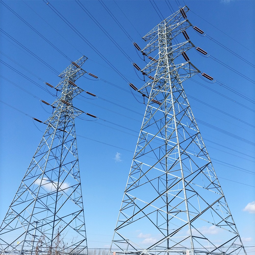
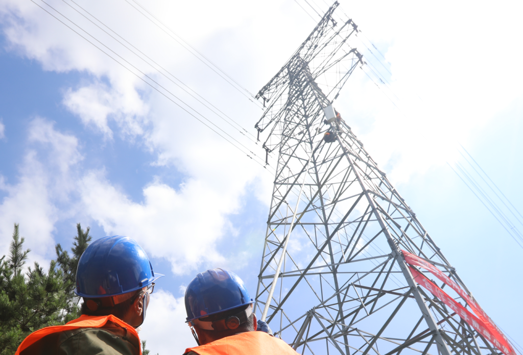
Our Hot Dip Galvanized Steel Lattice Power Transmission Towers represent the apex of utility grid structural engineering. Fabricated strictly from verified low-alloy high-strength Q235B, Q355B, Q420B, and Q420C steel plates and angles, these components undergo intense standardized mechanical formatting. They provide unparalleled structural support for overhead conductors, shield wires, optical ground wires (OPGW), and distribution hardware accessories across the world’s most severe environments.
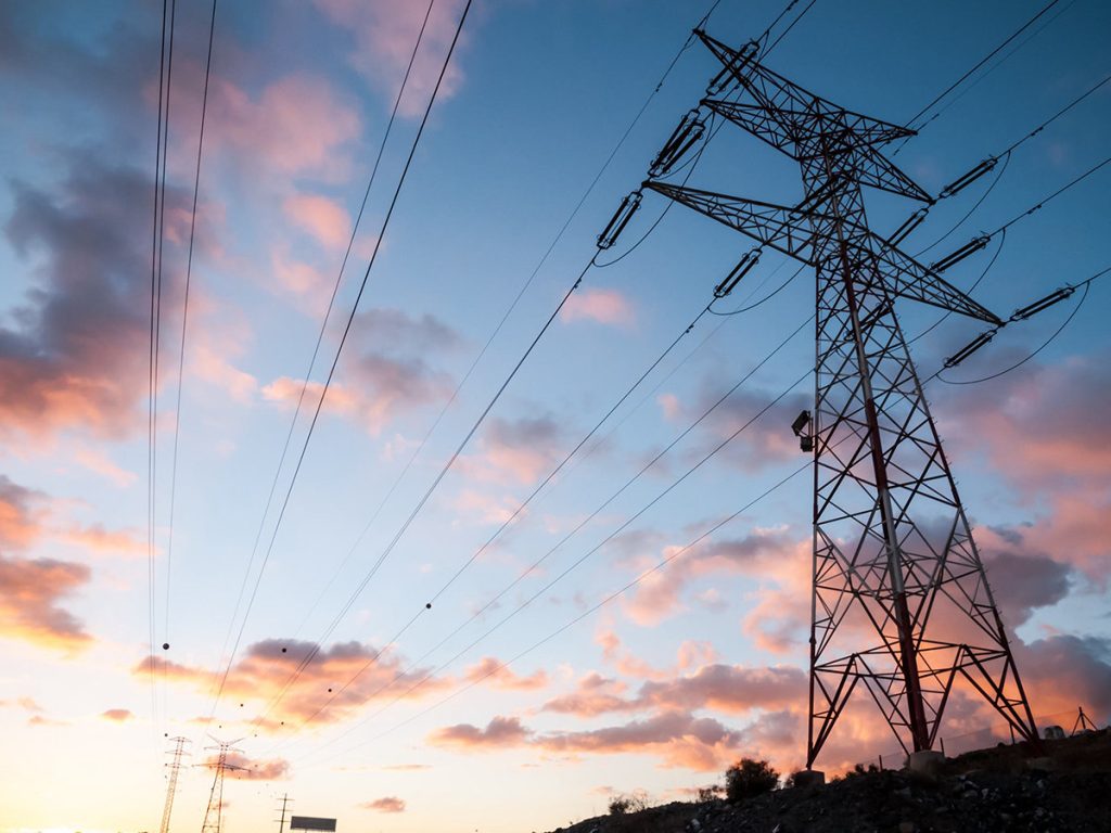
By implementing a specialized lattice self-supporting configuration, these structures optimize weight distribution while delivering massive geometric stiffness. This allows for exceptional span lengths across deep valleys, rivers, and rugged mountain terrains. The open truss architecture dramatically minimizes aerodynamic drag coefficients under high wind velocity scenarios, safeguarding continuity of critical national power lines.
1. Primary System Technical Parameters
| Technical Parameter Key | Standard Engineering Value | Regulatory Compliance & Certification |
|---|---|---|
| Main Material Composition | Premium Q235B / Q345B / Q355B / Q420B High Strength Structural Steel | GB/T 1591, ASTM A572, EN 10025 |
| Surface Treatment Method | Hot Dip Galvanization, Heavy Anti-corrosion Coating | ISO 1461, ASTM A123, GB/T 2694 |
| Design Service Life Span | Over 30 to 100 Years Outdoor Utility Service Span | ISO 9001 Structural Safety Framework |
| Available Voltage Grades | 35kV / 66kV / 110kV / 220kV / 500kV / 750kV / 1000kV | IEC 60826, ASCE 10-97 Standards |
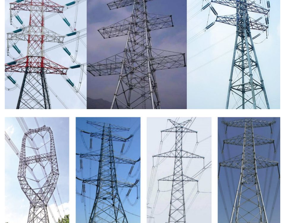
| Tower Geometrical Structure | Lattice Angle Steel, Triangular Truss, Tubular Hybrid Structure | Custom Engineering Drawing Formats |
| Wind Load Resistance Capacity | Grade 10 to Grade 12 Strong Wind Velocity Performance (30-50m/s) | ASCE 7-16, BS 6399 Aerodynamics |
| Seismic Acceleration Limit | Earthquake Resistance Performance up to Magnitude 8 (0.4g Accel.) | GB 50233, Eurocode 8 Seismic Code |
| Height Structural Flexibility | 15 meters up to 80 meters (Customized Extended Multi-Level Profiles) | DL/T 5219 Professional Grid Manual |
| Connection Mechanics | High-Strength Structural Bolt Joint Sets, Concentric Splice Plates | Grade 8.8 & 10.9 Fastener Specifications |
2. Advanced Material Metallurgy and Selection
The selection of underlying metallurgy dictates the overarching behavioral parameters of structural towers under static tensile loading, compressive stress loading, and temperature-induced physical expansion/contraction cycles. We procure premium killed steel coils and structural profiles characterized by strict element limitations to mitigate localized stress concentration and hydrogen-induced cracking risks during the intensive hot galvanizing stage.
| Steel Grade Standard | Carbon (C) Max % | Silicon (Si) Max % | Manganese (Mn) % | Phosphorus (P) Max % | Sulfur (S) Max % |
|---|---|---|---|---|---|
| Q235B (GB/T 700) | 0.20 | 0.35 | 1.40 max | 0.045 | 0.045 |
| Q355B (GB/T 1591) | 0.24 | 0.55 | 1.60 max | 0.035 | 0.035 |
| Q420B (High Tensile) | 0.20 | 0.50 | 1.70 max | 0.035 | 0.035 |
| ASTM A572 Gr. 50 | 0.23 | 0.40 | 1.35 max | 0.040 | 0.050 |
3. Mechanical Strength Matrix and Yield Boundaries
Q235B Properties
Yield Strength: ≥ 235 MPa
Tensile Ultimate: 370 – 500 MPa
Elongation Minimum: ≥ 26%
Q355B Properties
Yield Strength: ≥ 355 MPa
Tensile Ultimate: 470 – 630 MPa
Elongation Minimum: ≥ 22%
Q420B Properties
Yield Strength: ≥ 420 MPa
Tensile Ultimate: 520 – 680 MPa
Elongation Minimum: ≥ 19%
4. Advanced Hot-Dip Galvanized Anti-Corrosion Protection
The outdoor atmosphere presents significant corrosive challenges, including salt-laden sea sprays, high sulfur dioxide concentrations in industrial zones, and continuous UV breakdown. Our components undergo precise hot-dip galvanizing per ISO 1461, achieving full molecular metallurgical bonding between zinc layers and the steel substrate. This galvanic armor ensures self-healing protection if superficial mechanical damage occurs during transport or assembly field procedures.
| Component Material Thickness | Min Average Coating Thickness (μm) | Minimum Weight (g/m²) | Expected Adherence & Quality Testing Standard |
|---|---|---|---|
| Thickness ≥ 6mm | 86 μm | 610 g/m² | Preece Test copper sulfate dipping verification |
| 3mm ≤ Thickness < 6mm | 70 μm | 505 g/m² | Stripping method test evaluation per ASTM A90 |
| Thickness < 3mm | 55 μm | 395 g/m² | Magnetic flux gauge non-destructive monitoring |
| Fasteners and Hardware Set Components | 50 μm | 360 g/m² | Centrifugal spinning to guarantee uniform thread geometry |
5. Aerodynamic Engineering & Wind Velocity Adaptability
Lattice steel configuration delivers extreme aerodynamic optimization compared to solid concrete poles or heavy monopoles. The high spacing-to-member ratio lets catastrophic hurricane wind forces bypass the structural interior without generating low-frequency shedding vortex oscillations. This safeguards the geometric array and insulator string assemblies from destructive mechanical fatigue.
Wind Velocity Design Calculations (Standard ASCE 10-97 Framework)
The maximum overturning moment ($M_o$) and structural base shear ($V_b$) are dynamically processed utilizing advanced numerical computer algorithms:
Our standard design incorporates an explicit 1.5 safety scale multiplier over the maximum localized wind speed recorded in 100-year geological data intervals.
6. Lattice Tower Structural Classifications
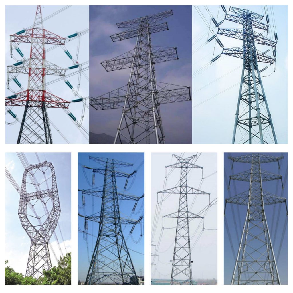
To build reliable overhead transmission lines, engineers must match the structural framework to specific electrical tension profiles, line angular deviations, and geographic clearance requirements. We manufacture 4 distinct structural classes:
| Tower Classification | Line Deviation Angle | Primary Mechanical Objective | Insulator String Layout |
|---|---|---|---|
| Tangent / Suspension Tower | 0° to 2° Max Deviation | Supports vertical gravity dead loads of conductors and wind force vectors perpendicular to the alignment. | Suspension Strings (I-type or V-type) |
| Angle / Tension Tower | 2° to 30° Deviation | Withstands continuous horizontal longitudinal loading forces stemming from conductor directional shifts. | Tension / Strain Assemblies |
| Dead-End / Anchor Structure | 30° to 90° Terminal Node | Positioned outside switching substations to support maximum structural line tension. | Heavy-duty Double Strain Systems |
| Transposition Tower | Special Project Layout | Alters the relative geometric placement of conductor phases to maintain balanced electrical impedance. | Multi-level Crossover Configuration |
7. Geotechnical Anchor Interfaces & Base Plate Structural Designs
The structural integrity of a transmission tower depends heavily on its concrete foundation interfaces. Our design office provides customized stub-angle anchor assemblies and high-performance base plates. These components transfer large compressive uplift and complex shear stresses deep into the subsurface earth strata.
| Foundation Design Variety | Applicable Subsurface Terrain | Anchor Rod Fastening Specs | Uplift Safety Coefficient |
|---|---|---|---|
| Rigid Poured Concrete Pad & Stem | Cohesive soils, standard firm clays, alluvial plains | ASTM F1554 Grade 55 / 105 Bolts | ≥ 2.2 |
| Deep Bored Micro-Piles | Soft wetlands, high water table, loose marine silt | Deformed high-yield threaded core bars | ≥ 2.5 |
| Rock Anchor Grout Framework | Exposed granitic rock, mountainous ranges | Epoxy-injected expansion anchor rods | ≥ 3.0 |
8. Full Manufacturing Process & Fabrication Pipeline
To prevent geometric misalignment during rapid on-site assembly, we utilize state-of-the-art CNC automated fabrication equipment. This production pipeline delivers absolute repeatability across thousands of duplicate angle steel structural profiles.
- Raw Material Inspection: Ultrasonic verification and heat-lot chemical spectrometry check.
- CNC Programming Layout: Directly loading structural software files into automated machinery.
- Hydraulic Shearing & Punching: High-speed linear profile trimming and clean bolt hole execution.
- Mechanical Bending: Precise alignment of localized gusset plates and cross-arm bends.
- Welding & Sub-Assembly: Carbon dioxide shielded arc welding strictly following AWS D1.1 specifications.
- Acid Pickling Cleanse: Removing superficial iron oxides via immersion in a 15% hydrochloric acid solution.
- Hot-Dip Galvanizing: Submerging components into molten pure zinc at 450°C.
- Cooling & Passivation: Applying liquid chemical passivation treatment to prevent early white rust formation.
- Pre-Assembly Matching Inspection: Constructing sample tower configurations at our facility to verify structural fitment.
9. Comprehensive Quality Assurance Tolerances
Our quality control technicians enforce strict tolerance criteria to eliminate field assembly rework and avoid dangerous structural eccentricities under full cable load conditions.
| Physical Measured Parameter | Maximum Permissible Variation | Metrology Inspection Instrument Used |
|---|---|---|
| Total Fabricated Member Length | ± 1.0 mm | Laser Distance Meter / Verified Steel Rule |
| Bolt Hole Center-to-Center Pitch | ± 0.5 mm | Digital Vernier Caliper Gauge |
| Cross Section Straightness Deviation | ≤ 1 / 1000 of independent profile span | Precision Dial Indicator & Taut Wire Reference |
| Bolt Hole Edge Distance Margin | + 2.0 mm / – 0.0 mm | Geometric Template Block Gauge |
| Overall Tower Verticality Axis Deviation | ≤ 1 / 2000 of total geometric tower elevation | Electronic Theodolite / Total Station Surveying |
10. High-Strength Fastener and Bolted Connection Systems
Lattice steel towers rely on friction and bearing connections between individual profiles. We provide high-strength structural bolt kits, complete with integrated spring washers and anti-theft locking nuts. This hardware prevents localized connection loosening caused by low-frequency eolian vibrations and conductor motion.
| Bolt Grade Specification | Nominal Diameter Options | Proof Load Rating (MPa) | Target Installation Torque (N·m) |
|---|---|---|---|
| Grade 8.8 Structural Core | M16, M20, M24 | 600 MPa | 190 – 320 N·m |
| Grade 10.9 Heavy Tension | M24, M27, M30 | 830 MPa | 450 – 710 N·m |
11. Global Custom Engineering & Site Adaptability
Every utility grid corridor presents unique spatial layout and topographic challenges. Our engineering design division utilizes industry-standard software suites (including PLS-CADD, PLS-TOWER, SAP2000, and AutoCAD). We generate structural designs optimized for specific geographic route criteria, climatic conditions, and physical clearing parameters.
12. Integrated Auxiliary Hardware & Fall-Protection Accessories
To ensure maximum utility safety during active maintenance operations, every tower configuration incorporates built-in auxiliary systems and permanent climbing hardware.
| System Sub-Component | Material Composition Specs | Primary Functional Purpose |
|---|---|---|
| Permanent Step Bolts | M16 Steel, Hot-Dip Galvanized | Provides safe, reliable climbing access on a designated tower leg, extending up to the highest peak. |
| Fall-Arrest Anchor Rail | Stainless Steel 304 / 316 Grade | Allows lineworkers to hook in safety lanyards, ensuring continuous protection against accidental falls. |
| Anti-Climbing Guard Frame | Barbed Wire Grid / Heavy Sheet Mesh | Prevents unauthorized public access, positioned 3 meters above base foundation level. |
| Bird Repellent Disc Assemblies | UV-Stabilized High-Density Polymers | Keeps large birds away from critical cross-arm insulation zones, preventing flashovers. |
13. Full-Scale Prototype Load Testing Criteria
We maintain an advanced testing ground capable of subjecting fully assembled structural steel prototypes to multi-directional load conditions. These testing procedures confirm the mathematical assumptions used in numerical PLS-TOWER computer analysis models.
| Testing Load Class | Applied Force Simulation Vector | Minimum Holding Duration |
|---|---|---|
| Normal Wind & Temperature Case | 100% full design dead weights + maximum transverse wind vectors applied at wire cross-arm nodes. | 60 Seconds continuous hold |
| Broken-Conductor Contingency | Simulates a sudden cable break by applying an unbalanced longitudinal pull at a single cross-arm. | 60 Seconds continuous hold |
| Ultimate Destructive Test | Incrementally increases simultaneous load vectors up to 150% structural capacity to identify the structural failure point. | Until physical buckling occurs |
14. Packaging, Container Loading, and Site Logistics
A single lattice tower consists of hundreds of separate angle steel members. To ensure efficient shipping and fast field sorting, we utilize an advanced component bundling system. This prevents member bending and protects the protective zinc galvanized coating during ocean transport.
Weatherproof Steel Banding
Members are grouped by structural sub-assembly and tightly bound using heavy-duty steel strapping. Wooden spacers are inserted between layers to prevent metal-on-metal friction damage.
Hard-Coded Component Stamping
Every individual steel piece features a permanently stamped identification code that matches the assembly manual. These codes remain completely legible after the hot-dip galvanizing process.
Heavy Hardware Storage
Connecting bolts, washers, nuts, and small gusset splice plates are packed into durable, seaworthy steel drums or reinforced wooden crates to eliminate transit loss risks.
15. Standardized On-Site Erection Framework
The modular construction of our lattice steel towers enables efficient on-site erection using standard field equipment. Construction crews can choose between two primary installation methodologies, depending on terrain accessibility and crane availability:
Method A
The Full Assembly Erection Procedure
The entire lattice tower body is pre-assembled flat on horizontal ground adjacent to the concrete foundation. Once configured and checked, a heavy-duty mobile crane hoists the complete structure into position over the foundation anchor rods. This approach maximizes ground-level working safety and speeds up installation schedules, provided the surrounding terrain is relatively flat and accessible for heavy machinery.
Method B
The Vertical Sectional / Piece-by-Piece Method
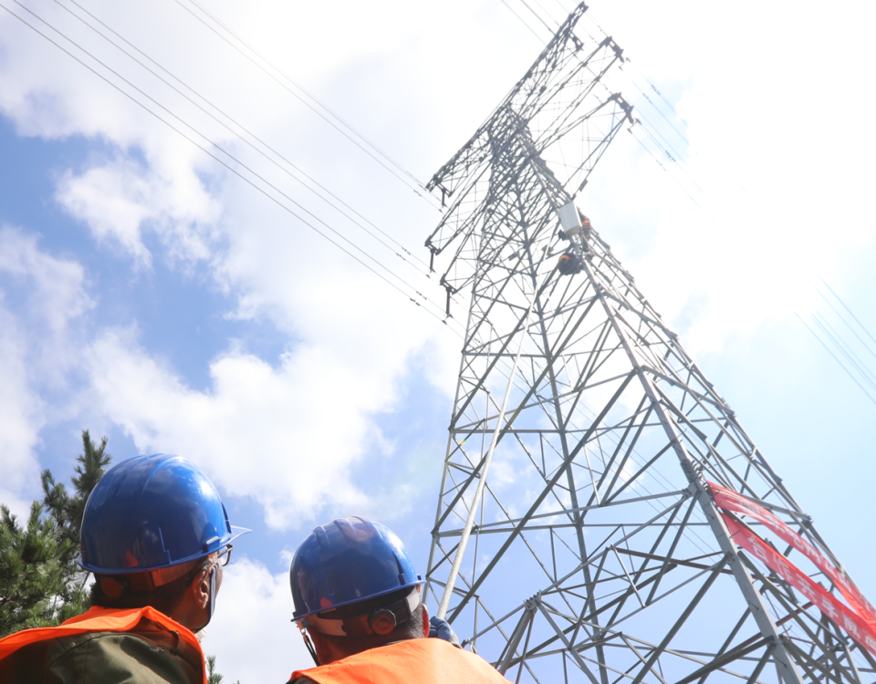
For remote mountainous sites or dense right-of-way corridors that restrict large crane access, crews build the structure vertically in sequential sections. Workers use a light gin pole or internal derrick system to lift individual angle profiles into place. Crews then secure the joints using calibrated manual torque wrenches before moving to the next level. This method adapts well to challenging terrain and minimizes environmental disruption around the base site.
16. Environmental Sustainability and Materials Circularity
Modern grid infrastructure developments must align with global green building standards and circular economy metrics. Our structural steel products contain up to 75% recycled scrap metal material input via modern Electric Arc Furnace (EAF) metallurgical production pathways. This drastically reduces the embodied carbon footprint of the final utility infrastructure.
At the end of the tower’s operational service life—often exceeding 80 years—the lattice steel components can be fully recovered and recycled. The materials can be melted down and reprocessed into new high-grade structural alloys without any reduction in mechanical property parameters. Furthermore, hot-dip galvanizing processes use natural zinc formulations that do not leach harmful organic chemicals into surrounding agricultural soils or regional water table systems.