
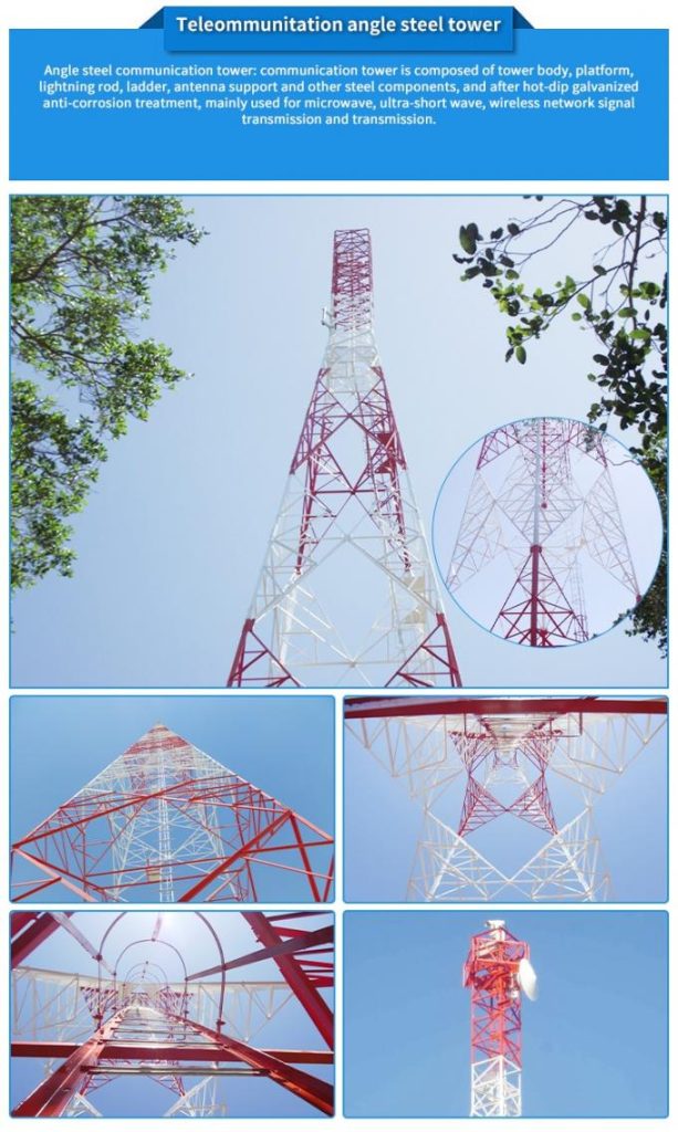
Self-Supporting Angular Telecom Towers

A Strategic Deep Dive into the Rural Wireless Steel Tower Business
September 8, 2025Polygonal Steel Distribution Poles for power transmission
October 3, 2025Engineering Connectivity: The Definitive Guide to Self-Supporting Angular Telecom Towers
Introduction: The Infrastructure of the Digital Age
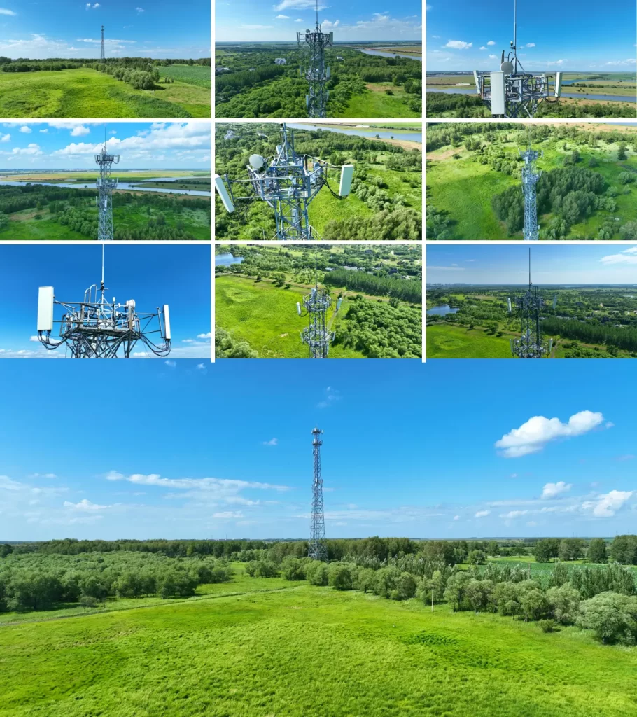
In the modern global economy, the backbone of commerce, communication, and connectivity is the robust, omnipresent cellular network. At the core of this network stands the Telecommunication Tower, a marvel of civil and structural engineering that must defy gravity, weather, and the ever-increasing demands of digital bandwidth.
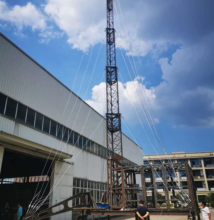
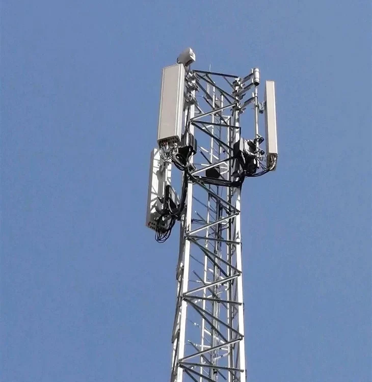
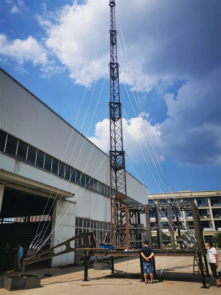
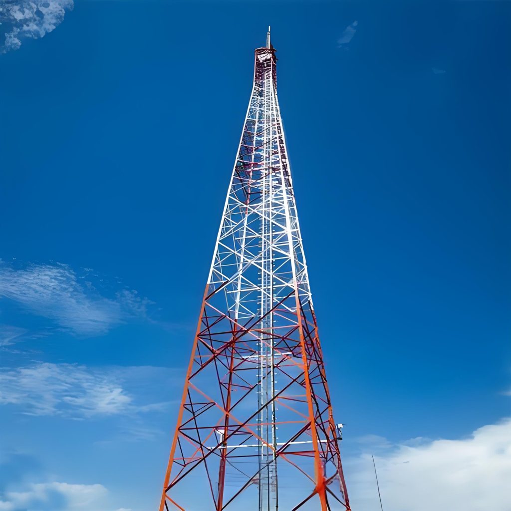
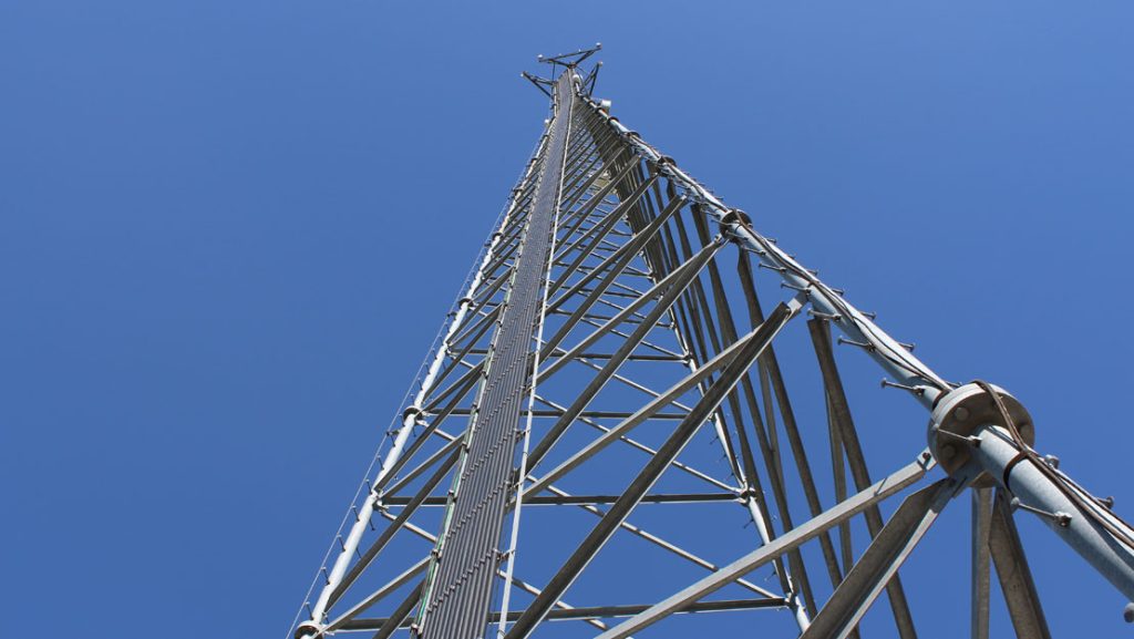
Our company specializes in the design, manufacture, and deployment of Self-Supporting Angular Telecom Towers—specifically, robust 3-legged and 4-legged lattice structures. These structures represent the pinnacle of engineered solutions for communication infrastructure, offering unmatched stability, strength-to-weight ratio, and longevity. Unlike guyed masts which rely on tension cables for support, our self-supporting towers require less real estate and provide superior resilience, making them the preferred choice for urban, suburban, and critical high-wind/high-load environments worldwide.
This comprehensive document serves as a testament to our expertise, detailing the structural philosophy, advanced material science, rigorous adherence to global standards (specifically TIA-222-G and TIA-222-H), and meticulous manufacturing processes that define our product quality. From the high-yield strength of our chosen Q-Series steel (Q235B, Q355B, Q420B) to the uncompromising corrosion protection offered by Hot Dip Galvanizing (ISO 1461, ASTM A123), every aspect of our towers is engineered for resilience, reliability, and guaranteed performance across the spectrum of customized design requirements.
I. The Structural Philosophy: Self-Supporting Lattice Towers
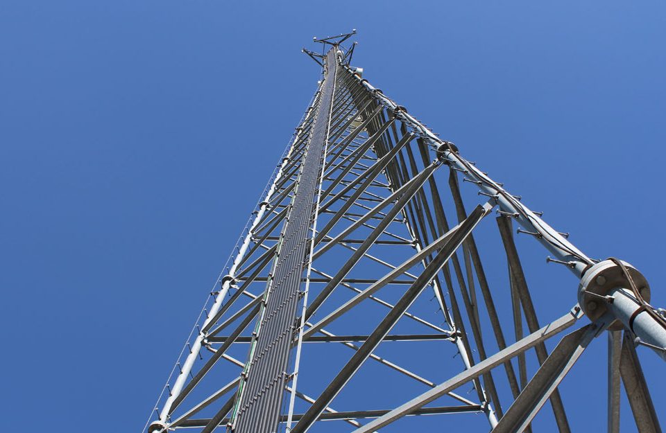
The design of a self-supporting lattice tower is a sophisticated balancing act between material economy and structural redundancy. Our focus on Angular Lattice Towers—meaning the primary members and bracing are constructed from angle steel sections (L-sections)—offers distinct engineering advantages over solid pole or monopole structures.
1.1 3-Legged vs. 4-Legged Configurations
The choice between a 3-legged and a 4-legged design is determined by the specific site conditions, required height, and total antenna loading. Both utilize the lattice framework to distribute forces efficiently.
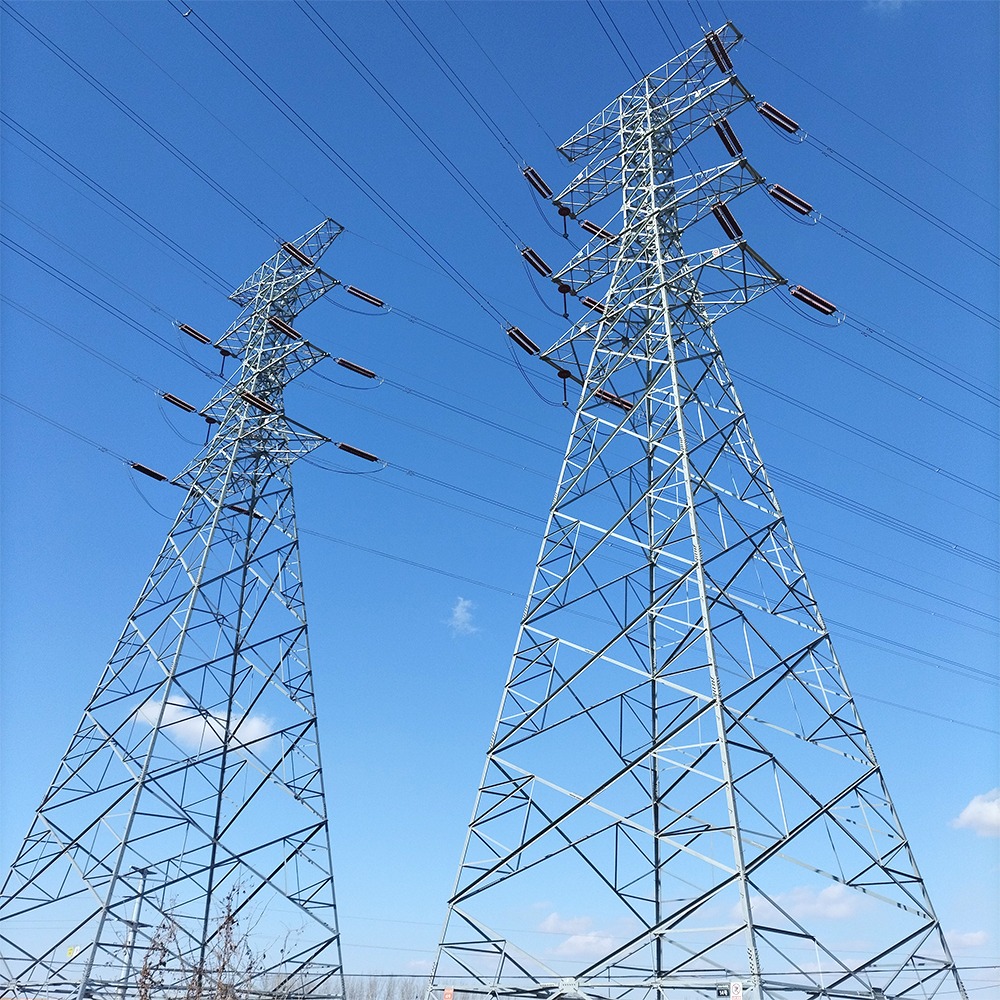
1.1.1 4-Legged Lattice Towers
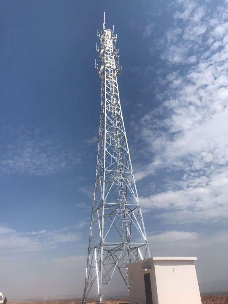
The 4-legged design is the traditional workhorse of the industry, renowned for its stability, especially in high-moment applications.
- Redundancy and Stability: Four legs inherently provide greater stability against torsional and lateral forces. The square or rectangular base footprint maximizes the resisting moment arm against overturning forces (wind).
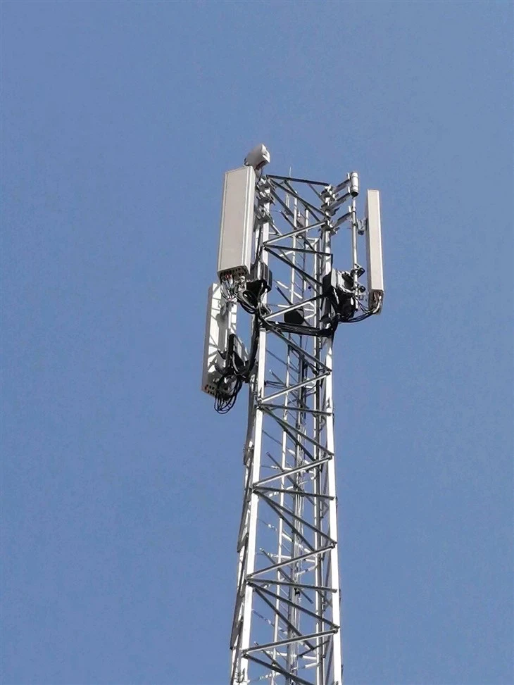
- Load Distribution: The four faces offer greater flexibility in mounting numerous antennas and ancillary equipment (e.g., microwave dishes, RRUs) with less interference, making them ideal for heavy loading scenarios and co-location sites where multiple carriers share the structure.
- Engineering Simplicity: The symmetry simplifies fabrication, analysis, and alignment during erection.
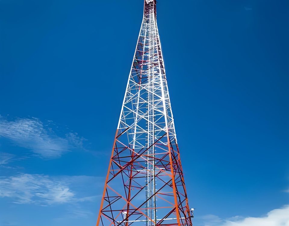
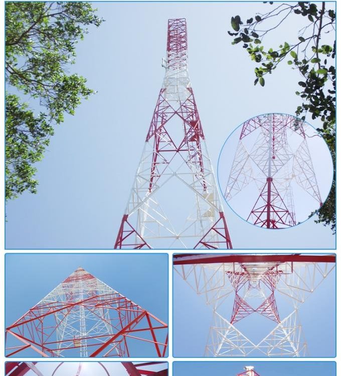
1.1.2 3-Legged Lattice Towers
The 3-legged triangular configuration has gained popularity due to its material and spatial efficiency.
- Cost Efficiency: With one less leg, the structure requires less steel and a smaller foundation footprint, leading to reduced material and construction costs.
- Wind Resistance: The triangular profile presents a smaller frontal area to the wind compared to a square section, potentially reducing the overall wind loading and thus the overall structural weight, especially at very tall heights.
- Space Saving: Ideal for sites with limited property boundaries or where environmental impact needs to be minimized.
In both configurations, the lattice structure—a triangulated web of angular steel bracing (diagonals and horizontals)—is key. This triangulated system ensures that external forces (like wind shear and gravitational load) are translated exclusively into axial tension and compression forces within the members. This is the most efficient way to utilize steel’s strength, leading to the exceptional strength-to-weight ratio characteristic of lattice towers.
1.2 The All-Bolted Connection Philosophy
Our towers employ a Plates connected with Bolts & Nuts connection system. This choice is a deliberate engineering decision driven by quality control, efficiency, and field execution requirements.
- Field Assembly Quality: Unlike field welding, which is highly dependent on environmental conditions and welder skill on-site, a bolted connection ensures consistent, measurable quality. Every component arrives pre-fabricated and pre-drilled, simplifying the erection process.
- Tolerance and Fit-Up: High-strength structural bolts (typically conforming to ASTM A325 or A490 equivalents) are manufactured to extremely tight tolerances. This ensures that the structure can be assembled quickly and accurately, provided the angular members and connection plates are fabricated and drilled with precision—a guarantee ensured by our ISO 9001 certified manufacturing process.
- Stress Management: Bolted connections are excellent at handling the cyclic fatigue loads common in telecom towers (caused by continuous wind buffeting) due to the controlled pre-tensioning of the bolts, which minimizes slippage and wear in the connection plates.
II. Material Science and Integrity: The Q-Series Steel Advantage
The longevity and performance of a telecom tower are fundamentally dictated by the quality and mechanical properties of its steel. We exclusively utilize high-quality, high-yield structural steel grades: Q235B, Q355B, and Q420B. The ‘Q’ designation refers to the minimum specified Yield Strength in megapascals (MPa).
2.1 Understanding the Q-Series Grades
| Material Grade | Minimum Yield Strength () (MPa) | Minimum Tensile Strength () (MPa) | Typical Applications in Tower Structure | Equivalent International Standard (Approx.) |
| Q235B | 235 | 370 – 500 | Bracing, secondary members, lighter towers. | ASTM A36 / EN S235J0 |
| Q355B | 355 | 470 – 630 | Main leg members, heavy bracing, medium-to-high height towers. | ASTM A572 Gr 50 / EN S355JR |
| Q420B | 420 | 520 – 680 | Critical lower leg sections of very tall towers, high-load environments. | ASTM A572 Gr 60 / EN S420 |
2.1.1 The Role of Yield Strength
The yield strength is the single most important parameter for tower design. Since a tower is essentially a compression-tension machine subjected to buckling forces (compression) and tensile forces, the higher the yield strength:
- The thinner the material that can be used for a given load, saving weight.
- The greater the effective safety factor against collapse under extreme wind/ice events.
The use of Q355B and Q420B for primary legs and high-stress members allows us to create structures that are lighter yet far stronger than those built exclusively with standard carbon steel like Q235B, optimizing material use while achieving superior performance in line with TIA-222 requirements.
2.1.2 Chemical Composition (Suffix B)
The suffix ‘B’ in the grade designation (e.g., Q355B) indicates that the steel has undergone specific quality control measures and guarantees minimum impact energy values at a temperature of . This ensures a minimum level of toughness, crucial for preventing brittle fracture, especially during cold-weather construction and operation. Furthermore, these steels exhibit excellent weldability, a factor vital for the pre-fabrication of base plates, anchor bolts, and reinforcement sleeves, processes certified by our AWS and CWB credentials.
III. Adherence to Global Standards: TIA-222-G and TIA-222-H
A telecom tower is a licensed structure, and its design integrity is entirely dependent on its adherence to recognized engineering codes. Our commitment to compliance with the Telecommunications Industry Association (TIA) TIA-222 standard—specifically revisions ‘G’ and ‘H’—ensures our products meet or exceed the world’s most stringent structural requirements.
3.1 TIA-222: The Structural Standard for Antenna Supporting Structures
TIA-222 is the definitive guide for calculating loads and determining the required strength of communication structures. It mandates a comprehensive analysis covering:
- Gravity Loads: Dead load (structure weight and fixed equipment).
- Wind Loads: The primary lateral force, calculated based on site-specific wind speed, exposure category, and the structure’s projected area.
- Ice Loads: Radial ice thickness and the resulting wind-on-ice loads, particularly critical in northern or mountainous regions.
- Seismic Loads: Forces resulting from ground motion, calculated according to site risk categories.
- Fatigue: Analyzing the stress cycles caused by repetitive wind loads to ensure the tower achieves its intended design life (e.g., 50 years).
3.2 Navigating the Shift from TIA-222-G to TIA-222-H
The transition from the TIA-222-G (published 2005) to the TIA-222-H (published 2017) standard marked a significant shift in structural analysis, and our design teams are fully proficient in both revisions.
| Feature | TIA-222-G (Older Revision) | TIA-222-H (Current Standard) | Impact on Tower Design |
| Design Methodology | Allowable Stress Design (ASD) with some Load and Resistance Factor Design (LRFD) elements. | Fully integrated LRFD methodology. | More accurate assessment of failure probability and material overstrength, often leading to slightly more efficient (lighter) designs if loads are known accurately. |
| Wind Maps | Based on extreme wind probability analysis. | Utilizes ASCE 7 wind speed maps and includes probability-based wind speed adjustment factors. | Incorporates recent climate data and refined turbulence modeling, often resulting in higher wind pressures in certain high-wind regions. |
| Ice Modeling | Uses a nominal radial ice thickness with a single combined loading scenario. | Uses a more complex, statistically derived ice thickness calculation and multiple combined loading cases (wind-on-ice, ice-only). | Requires designs to withstand a wider range of high-stress scenarios (e.g., heavy ice accretion combined with moderate winds). |
| Fatigue Analysis | Basic provision for fatigue. | Enhanced, mandatory fatigue assessment based on a defined wind spectrum over the tower’s lifespan. | Ensures the tower connection system (Bolts & Nuts) and critical member sizing can withstand long-term cyclic loading, crucial for preventing structural failure over decades. |
Our ability to certify designs under both G and H standards provides maximum flexibility for projects globally, catering to regions that have not yet adopted the latest TIA-222-H requirements. The precise calculation of design loads—which is why our height and wind speed are listed as “As per design”—is conducted using proprietary and industry-standard Finite Element Analysis (FEA) software, directly feeding into our manufacturing floor’s cutting and drilling programs.
IV. Manufacturing Precision, Protection, and Quality Systems
The theoretical strength derived from TIA-222 analysis and Q-series material specification is only realized through flawless execution in fabrication and protection against the environment.
4.1 Corrosion Protection: Hot Dip Galvanizing Excellence
The long-term service life of a steel lattice tower, often specified for 50+ years, is entirely dependent on its corrosion protection. We utilize Hot Dip Galvanizing (HDG) as the exclusive finishing standard, adhering strictly to ISO 1461 (International Standard) and ASTM A123 (North American Standard).
4.1.1 The Galvanizing Process and Standards
Hot dip galvanizing involves submerging the fabricated steel angular sections and connection plates into a bath of molten zinc (at approx. ). A metallurgical reaction occurs, forming a series of highly durable iron-zinc alloy layers bonded to the steel surface, covered by a layer of pure zinc.
| Standard | Description | Minimum Average Coating Thickness (m) | Typical Expected Service Life (Rural/Industrial) |
| ISO 1461 | Specifies requirements for the hot dip galvanized coatings on fabricated iron and steel articles. | Varies by steel thickness (e.g., to ). | 25 to 50+ years |
| ASTM A123 | Standard Specification for Zinc (Hot-Dip Galvanized) Coatings on Iron and Steel Products. | Varies by steel thickness (e.g., or to ). | 25 to 50+ years |
This zinc coating provides dual protection:
- Barrier Protection: The zinc layer physically shields the underlying steel from the corrosive atmosphere.
- Sacrificial (Cathodic) Protection: If the coating is scratched or damaged, the zinc preferentially corrodes, protecting the exposed steel until the zinc is completely consumed in the immediate area. This self-healing property is paramount for structures exposed to environmental abrasion.
Our quality process includes measuring the coating thickness using non-destructive magnetic gauges on every piece and ensuring the finish is free of bare spots, lumps, or other flaws that could compromise the 50-year design life.
4.2 Certifications: A Commitment to Quality, Safety, and Environment
Our operational excellence is quantified by our array of international certifications, which cover not just the final product quality but the entire scope of our business operations.
| Certificate | Scope | Importance in Tower Manufacturing |
| ISO 9001 | Quality Management System (QMS) | Guarantees consistency in design documentation, material traceability, dimensional accuracy (crucial for bolted connections), and adherence to specified standards (TIA-222). |
| ISO 14001 | Environmental Management System (EMS) | Demonstrates commitment to minimizing environmental impact, particularly important in the high-energy process of steel fabrication and the use of chemicals in the galvanizing process. |
| ISO 45001 | Occupational Health and Safety Management System (OH&S) | Ensures the highest safety standards in the factory and manages risks associated with lifting, cutting, welding (for base plates), and hot work. |
| AWS (American Welding Society) | Welding Quality and Procedure | Certifies our welding procedures and personnel for any component requiring shop welding (e.g., gusset plates, anchor assemblies), confirming compliance with US structural welding codes. |
| CWB (Canadian Welding Bureau) | Welding Quality and Procedure | Certifies our operations to Canadian welding standards (CSA W59), expanding our reach and competence in the North American market. |
These integrated management systems ensure that material selection (Q-series steel), design verification (TIA-222), and final finishing (HDG) are executed under a regime of continuous improvement and auditability.
V. Engineering the Custom Solution: Height, Wind, and Load
Our product line is defined by its customizability. Every tower is a unique solution to a unique set of challenges, synthesized through precise engineering analysis. The parameters “Height: As per design” and “Wind Speed: As per design” underscore our reliance on site-specific data and advanced computational modeling.
5.1 The Design Input Parameters
The initial phase of any project involves defining the site-specific loads:
- Site Location: Determines the seismic risk, ground conditions (foundation design), and critical environmental data (TIA-222 Wind Speed and Ice Thickness Maps).
- Antenna Loading: A precise inventory of all current and future equipment: size, weight, and mounting height/location of antennas, RRUs, microwave dishes, and platforms.
- Risk Category: TIA-222 defines risk categories (I, II, III, IV) based on the consequences of failure. Most telecom towers fall into Category II or III, which dictates the required design safety factors (load factors).
5.2 Finite Element Analysis (FEA) and Optimization
Using the site and load data, our engineering team constructs a 3D model of the proposed lattice structure. We then apply all combinations of forces (wind, ice, seismic, gravity) using advanced FEA software.
- P-Delta Effects: Analyzing the non-linear effects of axial compression and lateral deflection, particularly critical for tall, slender structures.
- Buckling Analysis: Ensuring that the compressive members (legs and bracing) do not fail by buckling—a sudden, catastrophic failure mode—which is directly influenced by the slenderness ratio of the angular steel sections.
- Connection Integrity: Verifying that the bolted connections and gusset plates can safely transfer the calculated forces between members without localized failure, often requiring dedicated sub-model analysis.
The output of the FEA guides the optimal choice of material grade (Q355B vs. Q420B) and the required size (angle leg length and thickness) for every single member of the structure, ensuring the final design is both safe and cost-effective.
VI. Consolidated Technical Parameters and Manufacturing Capabilities
The following table summarizes the key technical specifications and parameters that define the capabilities of our Self-Supporting Angular Telecom Tower products.
6.1 Technical Specifications Summary
| Parameter | Specification/Value | Applicable Standard/Design Criteria |
| Structure Type | Self-Supporting Lattice (3-legged and 4-legged) | Designed for structural efficiency and heavy antenna loading. |
| Primary Material Grades | Q235B, Q355B, Q420B | Determined by required Yield Strength () and structural demands. |
| Design Standard | TIA-222-G; TIA-222-H | Latest global standards for wind, ice, seismic, and fatigue loading. |
| Connection Type | Plates connected with High-Strength Bolts & Nuts | ASTM A325/A490 equivalent, ensuring high field assembly speed and reliability. |
| Corrosion Protection | Hot Dip Galvanizing (HDG) | ISO 1461 and ASTM A123, minimum 50-year service life assurance. |
| Design Height () | Custom (e.g., to ) | Determined by coverage area, clearance, and site environment. |
| Design Wind Speed () | Custom (e.g., to ) | Based on site-specific TIA-222 maps and exposure category. |
6.2 TIA-222 Load Factor () Illustration
TIA-222-H utilizes Load Factors to ensure a margin of safety against collapse. This is an illustration of how safety is built into the design equation , where is the calculated resistance and are the individual loads.
| Load Combination | TIA-222-H Load Factor (LRFD) | Description |
| Max Wind/Normal Operating | Assumes the tower is under maximum wind stress with all equipment installed. | |
| Max Ice/Minimum Wind | Critical for structural buckling; models heavy ice accretion with light associated wind. | |
| Dead Load Only | Checks structural integrity against gravity loads alone (e.g., foundation sizing). | |
| Seismic Load | Ensures stability during site-specific ground acceleration events. |
This systematic application of load factors across all stress scenarios is a testament to the rigorous, safety-first approach mandated by TIA-222, which is the cornerstone of our engineering practice.
VII. Conclusion: Building the Future of Global Communication
The Telecom Angular Tower is an indispensable component of the digital ecosystem. Our commitment to manufacturing these structures is rooted in a profound understanding of structural dynamics, material science, and global quality assurance.
By coupling the superior mechanical performance of Q-Series steel (Q355B, Q420B) with the design rigor of TIA-222-H, and protecting the investment with uncompromising Hot Dip Galvanizing (ISO 1461), we deliver structures that are not merely tall, but resilient, reliable, and fundamentally optimized for a 50-year service life. Our comprehensive certification portfolio, including ISO 9001, AWS, and CWB, assures clients worldwide that every bolt, plate, and angular member leaving our facility is engineered to the highest global standards for quality, safety, and precision.
In a world increasingly dependent on seamless digital communication, our self-supporting lattice towers stand as the robust, visible symbols of global connectivity—engineered today to support the technologies of tomorrow.


