
Steel Rooftop Antenna GSM Tower

220 kV Galvanized Lattice Steel Structure Tower Project | Schedules of Rates and Prices
May 15, 2025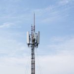
Guyed Wire Telescopic Antenna Carbon Steel Towers
June 5, 2025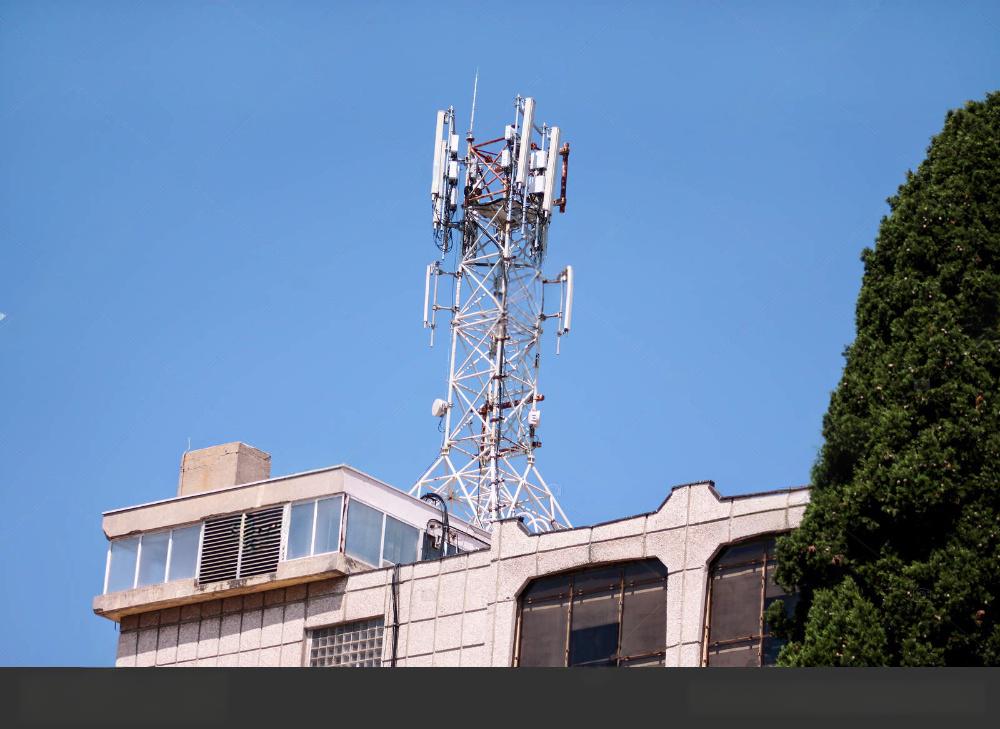
Scientific Analysis of Steel Rooftop Antenna GSM Towers
1. Structural Design and Material Properties of Steel Rooftop GSM Towers
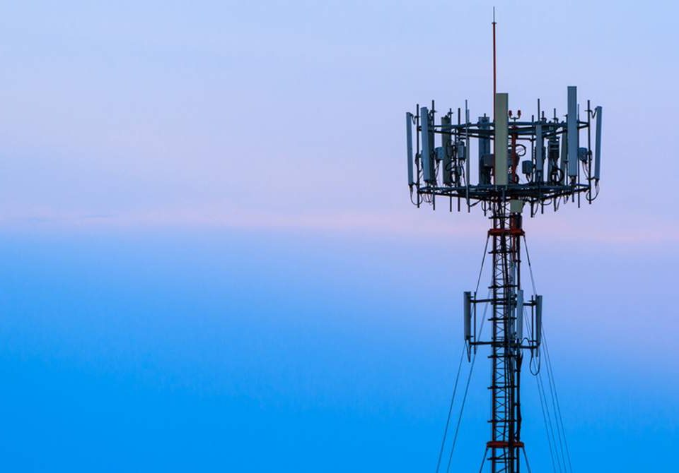
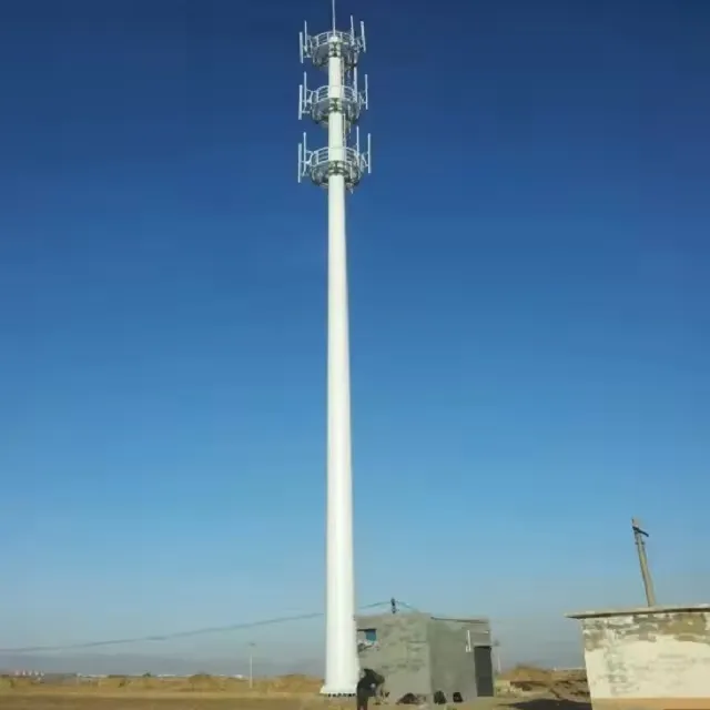
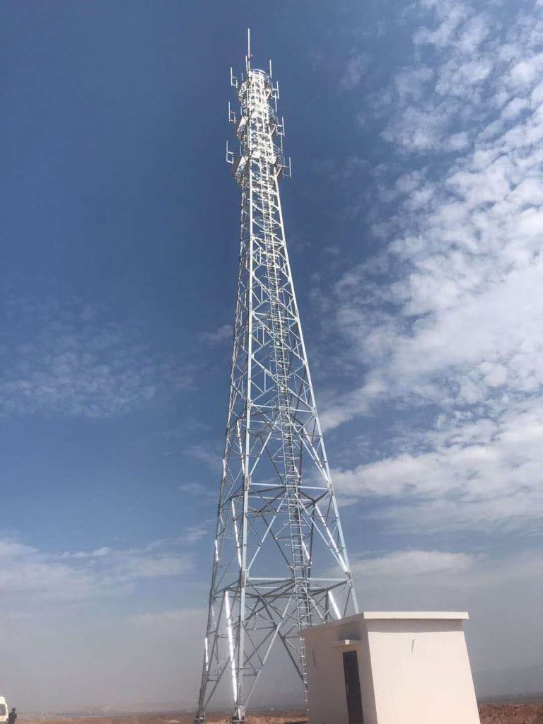
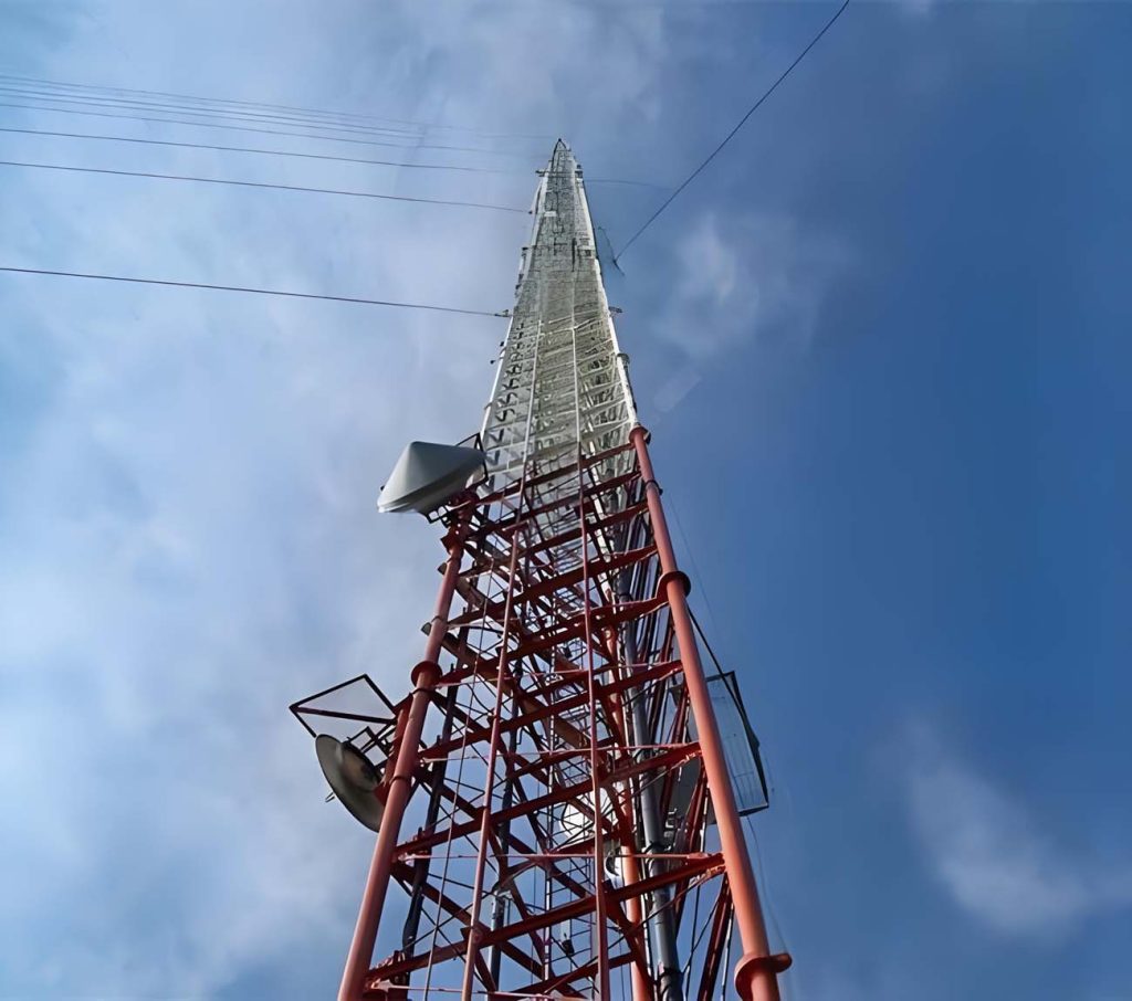
Steel rooftop GSM antenna towers are critical components of modern telecommunications infrastructure, particularly in urban environments where space constraints and aesthetic considerations necessitate compact, efficient designs. These towers are typically constructed using high-strength steel alloys, such as Q235, Q345, or Q420, which offer excellent tensile strength, corrosion resistance, and durability under dynamic loading conditions. The choice of steel is driven by its ability to withstand environmental stressors, including wind loads, seismic activity, and ice accumulation, while maintaining structural integrity over extended periods. The towers are often designed as lattice structures (angular or tubular) or monopoles, with lattice towers being more common for rooftop applications due to their lightweight nature and ease of installation on building rooftops.
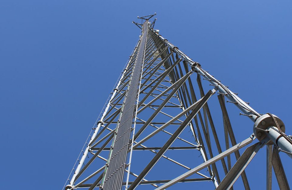
The structural design of a steel rooftop GSM tower involves a complex interplay of engineering principles, including static and dynamic load analysis, finite element modeling, and compliance with international standards such as EIA/TIA-222 or Eurocode. Lattice towers are typically composed of hot-rolled angle sections connected by bolts, with bracing systems to enhance torsional stiffness. The foundation design is critical, as rooftop towers must transfer loads to the building’s structural framework without exceeding the allowable stress capacity of the roof. Advanced computer programs, such as STAAD.Pro or ASMTower, are used to simulate load conditions, including self-weight, antenna loads, wind, and ice, ensuring the tower meets safety and performance requirements. Hot-dip galvanization is commonly applied to steel components to prevent corrosion, extending the service life to 20–30 years under typical urban conditions.
The primary advantage of steel rooftop towers is their adaptability to urban settings, where ground space is limited. Unlike guyed masts, which require extensive land for guy wires, rooftop towers are self-supporting or minimally braced, making them ideal for densely populated areas. However, their design must account for the building’s structural capacity, as excessive loading can compromise the roof’s integrity. Finite element analysis (FEA) is employed to model the tower’s response to wind-induced vibrations, which are a primary concern due to the high elevation and exposure of rooftop installations. The use of 3D beam and truss elements in FEA allows engineers to predict stresses, deflections, and buckling behavior, ensuring the tower remains stable under extreme conditions.
|
Parameter
|
Description
|
Typical Values
|
|---|---|---|
|
Material
|
High-strength steel
|
Q235, Q345, Q420
|
|
Yield Strength
|
Minimum stress before deformation
|
235–420 MPa
|
|
Tower Height
|
Range for rooftop applications
|
5–20 m
|
|
Foundation Type
|
Single footing or raft
|
Depends on roof capacity
|
|
Corrosion Protection
|
Hot-dip galvanization
|
80–100 µm coating thickness
|
2. Load Analysis and Environmental Considerations
The structural integrity of steel rooftop GSM towers is heavily influenced by environmental loads, particularly wind and ice, which can significantly alter the tower’s aerodynamic profile and loading conditions. Wind loads are calculated using standards like EIA/TIA-222, which specify wind speed zones (e.g., 39 m/s or 55 m/s) and corresponding drag coefficients. The drag coefficient depends on the tower’s geometry and antenna arrangement, with lattice towers typically exhibiting lower drag than monopoles due to their open structure. For a 10-meter rooftop lattice tower, wind loads can generate base shear forces of 10–20 kN and overturning moments of 50–100 kNm under a 50 m/s wind speed, depending on the antenna configuration.
Ice accumulation is another critical factor, particularly in cold climates. Ice loads increase the tower’s effective surface area, amplifying wind-induced forces. For example, a study on a 60-meter triangular lattice tower showed that ice loads combined with wind loads increased leg forces by 15–20% and bracing forces by 10–15% compared to wind-only conditions. To mitigate this, engineers reduce wind load calculations by a factor (typically 0.75–0.85) when ice is present, as per standards like EN 1993-3-1. Rooftop towers, being shorter (5–20 m), experience less severe ice loading but must still account for combined effects to prevent buckling of slender members.
Seismic loading is also a concern, particularly in earthquake-prone regions. Time history analysis, using recorded or synthesized accelerograms, simulates the tower’s response to ground motion. For instance, a study on a self-supporting rooftop tower equipped with seismic accelerometers identified five bending modes with natural frequencies ranging from 1.5 to 5 Hz, closely matching finite element predictions. Viscous dampers can reduce dynamic amplification, lowering peak displacements by 20–30%. The use of semi-rigid connections, rather than assumed hinged joints, enhances stability by reducing unwanted degrees of freedom, as demonstrated in analyses of 50–90 m guyed towers adapted for rooftop applications.
|
Load Type
|
Typical Value
|
Impact on Tower
|
|---|---|---|
|
Wind Load
|
39–55 m/s
|
Shear: 10–20 kN, Moment: 50–100 kNm
|
|
Ice Load
|
10–20 mm thickness
|
Increases leg forces by 15–20%
|
|
Seismic Load
|
0.1–0.3g acceleration
|
Displacement: 10–50 mm
|
|
Self-Weight
|
500–2000 kg
|
Contributes to foundation load
|
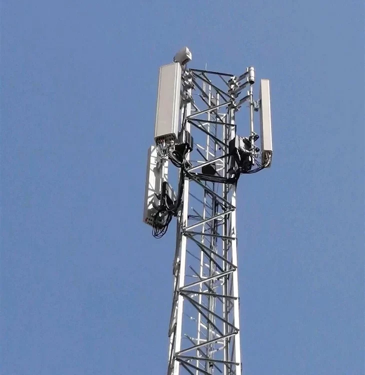
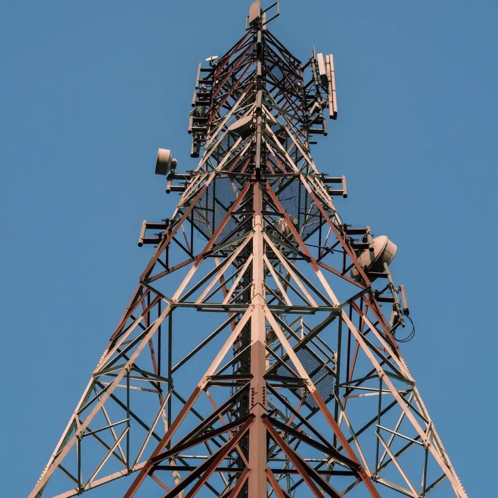
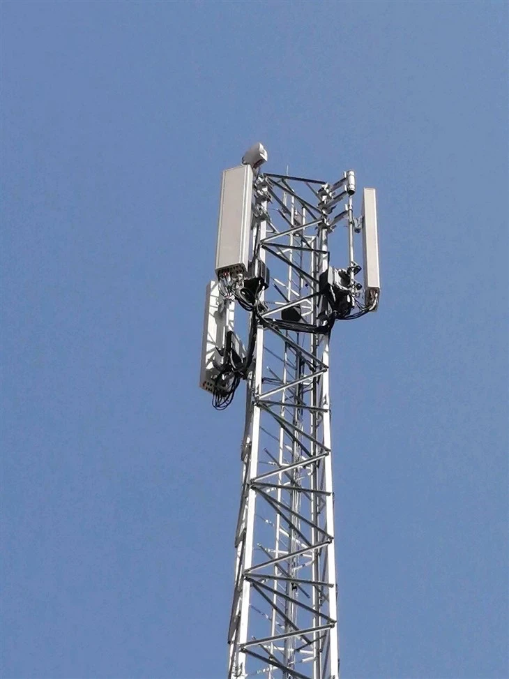
3. Antenna Arrangement and Its Impact on Performance
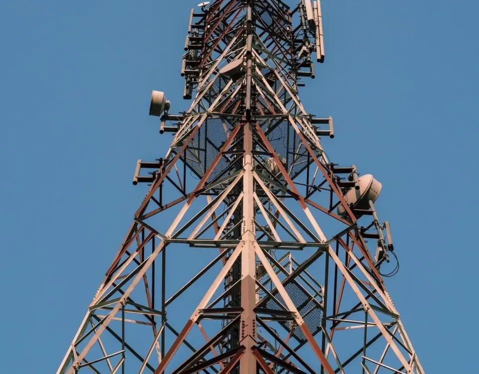
The arrangement of antennas on a steel rooftop GSM tower significantly affects its structural and aerodynamic performance. Antennas are typically mounted at the top to maximize signal coverage, but their number, form, and layering influence wind load sensitivity and signal quality. A study on 5G-upgraded towers found that increasing the number of antennas per layer reduces the need for multiple layers, thereby lowering the overturning moment coefficient by approximately 50% compared to multi-layered configurations. For instance, a tower with four antennas per layer experiences a drag coefficient of 1.2–1.5, while a multi-layered setup with the same number of antennas may increase the coefficient to 1.8–2.0 due to increased surface area.
The antenna arrangement also affects signal propagation. GSM antennas operate within frequency ranges of 790–880 MHz and 870–960 MHz, with higher frequencies requiring precise alignment to maintain line-of-sight communication. In urban environments, rooftop towers must contend with multipath effects caused by reflections from buildings. Antennas with strong multipath suppression, such as those with high gain roll-off factors, can reduce the root mean square (RMS) multipath error at L1/E1 frequencies to 0.1–0.3 m, improving signal-to-noise ratio (SNR) by 5–10 dB compared to standard patch antennas.
The placement of antennas on rooftop towers must balance structural and electromagnetic considerations. For example, a uniform antenna arrangement minimizes wind direction sensitivity, reducing lateral force coefficients by 10–15%. However, asymmetrical arrangements may be necessary to optimize coverage in specific directions, increasing design complexity. Advanced simulation tools, such as ASMTower, calculate wind loads on each antenna and perform P-delta analysis to ensure stability under combined loading conditions. The table below compares different antenna configurations.
|
Configuration
|
Drag Coefficient
|
Overturning Moment (kNm)
|
SNR Improvement (dB)
|
|---|---|---|---|
|
Single Layer, 4 Antennas
|
1.2–1.5
|
50–80
|
5–7
|
|
Multi-Layer, 4 Antennas
|
1.8–2.0
|
100–150
|
3–5
|
|
Asymmetrical, 4 Antennas
|
1.5–1.7
|
80–120
|
4–6
|
4. Electromagnetic and RF Performance
GSM rooftop towers are designed to support antennas that facilitate reliable wireless communication. The antennas’ electromagnetic performance is governed by parameters such as gain, beamwidth, and radiation pattern. Typical GSM antennas have a gain of 15–18 dBi and a horizontal beamwidth of 60–90 degrees, optimized for urban coverage. The power density of RF emissions from rooftop antennas is a critical concern due to public health considerations. Measurements in Accra, Ghana, showed that rooftop sites inside buildings had maximum power densities levels of 2.46 × 10⁻² W/m², well below the International Commission on Non-Ionizing Radiation Protection (ICNIRP) guideline of 4.5 W/m² for 900 MHz. Outside buildings, levels were even lower, ranging from 7.44 × 10⁻⁵ to 3.35 × 10⁻³ W/m².
The introduction of 5G technology has increased the complexity of antenna systems, with massive MIMO (Multiple Input Multiple Output) configurations requiring multiple antennas to enhance spectral efficiency. A study comparing GSM with space-time coding (STC) and conventional GSM showed that STC improved SNR by 3–5 dB, enhancing data rates by 20–30% in urban settings. However, the additional antennas increase wind loads, necessitating robust structural designs. For rooftop towers, the use of magneto-electric dipole antennas offers low back radiation and symmetrical E- and H-plane patterns, reducing interference and improving coverage compared to conventional patch antennas.
The height of the antenna above the rooftop is a key factor in determining coverage range. A 10-meter tower with antennas at 15 meters above the building can achieve a coverage radius of 2–5 km, depending on transmitter power (typically 20–50 W) and landscape features. Higher antennas reduce signal obstruction by buildings, but they also increase wind loads, requiring careful structural optimization. The table below summarizes RF performance metrics.
|
Metric
|
Value
|
Impact
|
|---|---|---|
|
Antenna Gain
|
15–18 dBi
|
Enhances coverage range
|
|
Power Density
|
10⁻⁵–10⁻² W/m²
|
Below ICNIRP guidelines
|
|
Coverage Radius
|
2–5 km
|
Depends on height and power
|
|
SNR (with STC)
|
+3–5 dB
|
Improves data rates by 20–30%
|
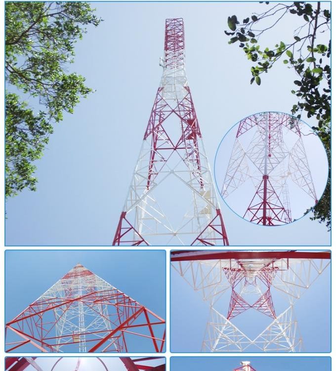
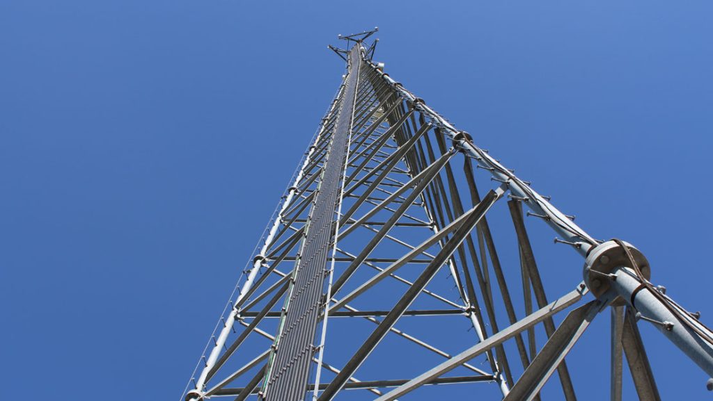
5. Comparison of Rooftop Towers with Other Tower Types
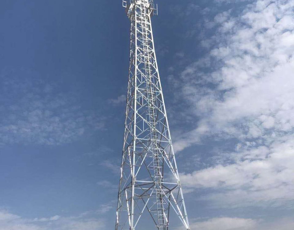
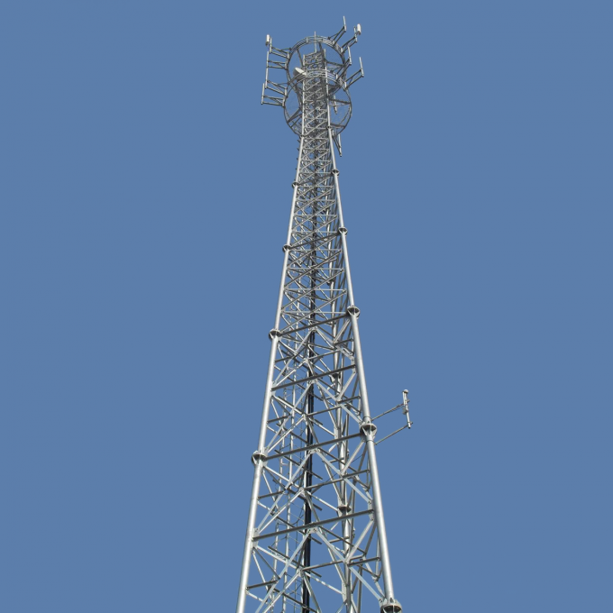
Steel rooftop GSM towers differ significantly from ground-based guyed masts and self-supporting towers in terms of design, installation, and performance. Guyed masts, typically 50–150 meters tall, rely on tensioned cables for stability, making them unsuitable for urban rooftops due to space requirements for guy wires. Self-supporting towers, often 15–150 meters, are more robust but require larger foundations, increasing costs and making them less feasible for rooftop applications. Rooftop towers, with heights of 5–20 meters, are lightweight (500–2000 kg) and designed to integrate with building structures, minimizing ground space usage.
Structural analysis reveals that rooftop towers experience lower base shear forces (10–20 kN) compared to guyed masts (20–50 kN) under similar wind conditions due to their shorter height. However, they are more sensitive to roof capacity constraints, with allowable stresses typically limited to 0.5–1.5 kN/m². Guyed masts, while cost-effective for rural areas, have higher maintenance costs due to cable tension adjustments, whereas rooftop towers benefit from easier access for maintenance. Monopoles, another alternative, are aesthetically pleasing but less stable under high wind loads, with buckling risks 10–15% higher than lattice towers for equivalent heights.
Electromagnetically, rooftop towers excel in urban environments due to their elevated position, reducing multipath effects compared to ground-based towers. However, they face challenges from nearby structures, which can cause signal reflections. The table below compares key parameters across tower types.
|
Tower Type
|
Height Range (m)
|
Base Shear (kN)
|
Installation Cost (USD)
|
Maintenance Complexity
|
|---|---|---|---|---|
|
Rooftop Tower
|
5–20
|
10–20
|
10,000–30,000
|
Low
|
|
Guyed Mast
|
50–150
|
20–50
|
20,000–50,000
|
High
|
|
15–150
|
15–40
|
30,000–100,000
|
Moderate
|
|
|
10–50
|
12–25
|
15,000–40,000
|
Low
|
6. Advances in Design and Optimization Techniques
Modern design of steel rooftop GSM towers leverages advanced computational tools to optimize structural and electromagnetic performance. Software like ASMTower performs P-delta analysis, accounting for second-order effects due to large deformations under wind loads. This is critical for rooftop towers, where deflections must be limited to 10–20 mm to prevent antenna misalignment. The software also generates 3D models, color-coding members based on utilization ratios (e.g., 0.8–1.0 for safe design), allowing engineers to identify overstressed components.
Finite element models (FEM) have evolved from simple truss assumptions to complex 3D beam and truss combinations, capturing semi-rigid connection behavior. A study on 50–90 m towers adapted for rooftop use showed that 3D beam models reduced predicted deflections by 10–15% compared to truss-only models, improving accuracy. For 5G applications, global optimization techniques, such as nature-inspired algorithms combined with surrogate modeling, reduce computational costs by 30–40% while ensuring antenna performance across broad parameter ranges.
The integration of 5G antennas has necessitated upgrades to existing 4G towers, increasing wind loads by 20–30% due to additional equipment. Numerical simulations show that optimizing antenna arrangement (e.g., increasing antennas per layer) can mitigate this increase, maintaining structural safety. The table below highlights optimization outcomes.
|
Optimization Technique
|
Benefit
|
Reduction in Cost/Time
|
|---|---|---|
|
P-Delta Analysis
|
Reduces deflection errors
|
10–15%
|
|
3D Beam FEM
|
Improves stress prediction
|
10–20%
|
|
Surrogate Modeling
|
Lowers computational time
|
30–40%
|
|
Antenna Arrangement Optimization
|
Reduces wind load
|
15–25%
|
7. Safety and Regulatory Considerations
Safety is paramount in the design and operation of steel rooftop GSM towers, given their proximity to urban populations. Structural safety is ensured by adhering to standards like EIA/TIA-222, which specify safety factors of 1.5–2.0 for ultimate loads. RF radiation exposure is another concern, with ICNIRP guidelines limiting public exposure to 4.5 W/m² at 900 MHz. Measurements from rooftop sites consistently show compliance, with power densities levels 100–1000 times below limits, ensuring minimal health risks.
Maintenance involves regular inspections for corrosion, weld integrity, and bolt tightness, with rooftop towers benefiting from easier access compared to ground-based structures. However, the risk of roof overloading requires periodic structural assessments, particularly after antenna upgrades. Regulatory compliance also includes aesthetic considerations, with stealth designs (e.g., disguised as chimneys) used to minimize visual impact in urban areas. The table below summarizes safety metrics.
|
Safety Aspect
|
Requirement
|
Typical Compliance
|
|---|---|---|
|
Structural Safety Factor
|
1.5–2.0
|
Met with Q345 steel
|
|
RF Exposure Limit
|
4.5 W/m²
|
10⁻⁵–10⁻² W/m²
|
|
Deflection Limit
|
10–20 mm
|
Achieved with P-delta analysis
|
|
Corrosion Resistance
|
20–30 years
|
Ensured by galvanization
|
8. Future Trends and Challenges
The evolution of steel rooftop GSM towers is driven by the transition to 5G and beyond, requiring higher antenna densities and advanced materials. Composite materials, such as carbon fiber-reinforced polymers, are being explored to reduce weight while maintaining strength, potentially lowering tower mass by 20–30%. However, their high cost (2–3 times that of steel) limits widespread adoption. Smart towers equipped with sensors for real-time load monitoring are also emerging, improving maintenance efficiency by 15–20%.
Challenges include managing increased wind loads from 5G antennas and ensuring compatibility with existing building structures. Retrofitting older rooftops for 5G upgrades often requires reinforcement, increasing costs by 10–20%. Additionally, urban densification necessitates smaller, more discreet towers, driving innovations in stealth technology. The table below outlines future trends.
|
Trend
|
Impact
|
Challenge
|
|---|---|---|
|
Composite Materials
|
Reduces weight by 20–30%
|
High cost
|
|
Smart Sensors
|
Improves maintenance efficiency
|
Integration complexity
|
|
Stealth Designs
|
Enhances aesthetics
|
Increases design cost
|
|
5G Upgrades
|
Improves data rates
|
Higher wind loads
|
steel rooftop GSM towers are a cornerstone of urban telecommunications, balancing structural, electromagnetic, and regulatory requirements. Their design requires sophisticated modeling, material selection, and optimization to ensure reliability and safety in dynamic urban environments.