
Technical Analysis of 110kV to 750kV Transmission Line Towers
Visual Analysis for Determining Transmission Line Voltage
December 3, 2025
A Deep Technical Analysis of Transmission Line Tower Manufacturing Standards
December 10, 2025The Forge of Resilience: Technical Analysis of the Manufacturing Processes for $110 \text{ kV}$ to $750 \text{ kV}$ Transmission Line Towers
The fabrication of overhead transmission line towers, spanning the operational voltage spectrum from the essential $110 \text{ kV}$ corridors to the colossal $750 \text{ kV}$ EHV backbone structures, is a specialized field of structural engineering that transcends standard steel construction. It is an industrial process rooted deeply in metallurgical science, geometric precision via CNC automation, and specialized corrosion engineering, where the final product is not merely a steel frame but a meticulously designed and protected truss system destined for a service life often exceeding half a century in the harshest global environments. The manufacturing process must not only transform raw steel into thousands of unique, precisely dimensioned members but must also guarantee a seamless, stress-free fit during site erection, followed by an unparalleled degree of corrosion resistance. The scaling of complexity from a standard $110 \text{ kV}$ tower to a $750 \text{ kV}$ structure, with its exponentially higher mass, increased member thickness, and geometric intricacy, dictates a move from conventional fabrication tolerances to near-aerospace-level precision, heavily reliant on integrated automation and stringent quality control protocols.
1. The Metallurgical Blueprint: Material Selection and Preparation
The foundation of tower fabrication rests entirely upon the integrity and certification of the incoming raw material. The scale and stress levels associated with high-voltage structures, particularly those designed for $500 \text{ kV}$ and $750 \text{ kV}$ lines, necessitate the use of specialized structural steel grades that offer an optimal balance of high yield strength, excellent weldability (for plates and base sections), and favorable chemical composition for the subsequent hot-dip galvanization process.
Scaling of Steel Grades with Voltage
As the tower height, span length, and conductor loads increase with voltage, the core structural members—primarily the legs, main diagonals, and cross-arms—experience dramatically higher axial compression and tensile forces. This necessitates a shift in the primary steel alloy:
-
HV Towers ($110 \text{ kV}$ to $220 \text{ kV}$): Often predominantly utilize standard structural steel grades (e.g., Q235 or equivalent ASTM A36/Grade 36), supplemented by higher-strength material for main legs and critical joints.
-
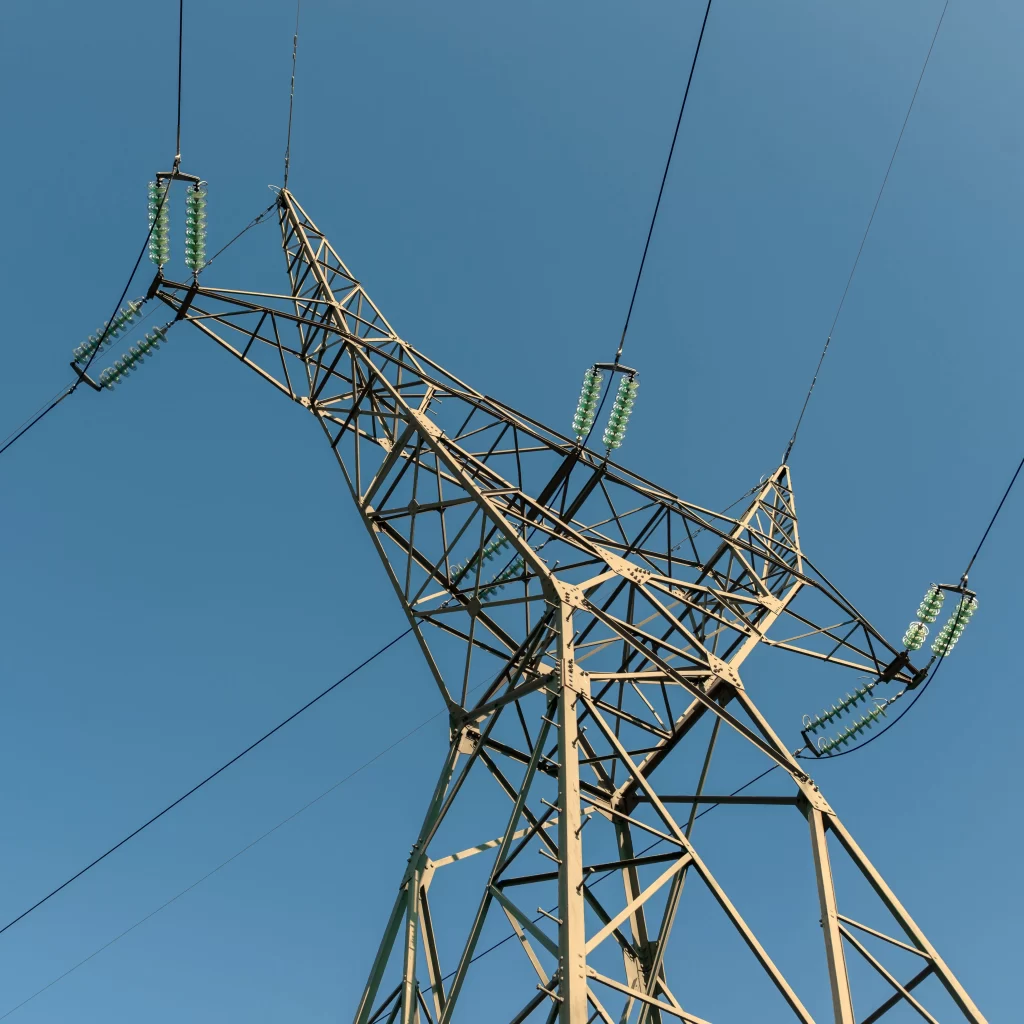
EHV/UHV Towers ($500 \text{ kV}$ to $750 \text{ kV}$): The massive, critical members must employ high-strength low-alloy (HSLA) steel (e.g., Q345/equivalent ASTM A572 Grade 50 or higher). This grade provides significantly higher yield strength, allowing the designers to maintain a manageable cross-sectional area and weight while absorbing enormous structural loads. The chemical composition of these steels must be meticulously controlled, particularly carbon equivalents ($\text{CE}$) and silicon content, as both influence formability and, critically, the quality of the final galvanized coating.
The initial stage requires the factory to perform comprehensive Material Verification. This goes beyond checking the mill test certificates (MTCs); it involves routine internal quality checks, including chemical composition analysis (using spectrometry) and mechanical testing (tensile and yield strength tests) on samples of incoming batches. This rigorous process is essential to guarantee that the actual properties of the steel meet the assumptions used in the complex structural analysis (finite element modeling) performed by the tower designer. Any deviation in yield strength could compromise the buckling resistance of the structure, leading to catastrophic failure under design wind or ice loading.
Surface Preparation and Initial Handling
Before any cutting or shaping occurs, the raw steel members (angle irons, plates, channels) must undergo surface preparation. Standard mill-rolled steel is covered in mill scale—a flaky, iron oxide layer—which is unsuitable for subsequent processing and disastrous for galvanization. Initial cleaning often involves shot blasting or abrasive cleaning to remove mill scale and surface contaminants, providing a clean, reactive metal surface for subsequent operations. Furthermore, the handling of the material must be rigorously controlled throughout the fabrication process. Contact with corrosive chemicals, grease, or paint must be strictly avoided, as these contaminants can interfere with the chemical pre-treatment required for hot-dip galvanization, leading to localized areas of poor zinc adhesion and premature corrosion in the field. The integrity of the final protective coating is intrinsically linked to the cleanliness of the steel surface from the moment it enters the fabrication facility.
2. Geometric Precision: Automation in Cutting, Punching, and Forming
The structural efficacy of a lattice tower hinges entirely on the perfect geometric fit of thousands of unique members. Tower fabrication demands that bolt holes align precisely with corresponding holes in mating members, often across spans of several meters. This level of precision, particularly for the large, high-redundancy $750 \text{ kV}$ structures, is achievable only through the mandatory adoption of Computer Numerically Controlled (CNC) automation.
The Supremacy of CNC Angle Line Processing
The core of modern tower fabrication is the CNC Angle Line Processing System. These automated lines ingest raw angle or plate stock and perform all necessary operations—punching, drilling, numbering, and cutting—without manual intervention.
-
Punching vs. Drilling: Historically, bolt holes were often punched due to speed. However, for high-strength steel members (Q345/Grade 50) and critical connections in EHV towers, drilling is preferred or mandated. Punching introduces localized cold-working and micro-cracks around the hole perimeter, reducing the fatigue resistance of the member and introducing residual stress. Drilling, while slower, provides a smoother hole surface and minimizes material damage, which is critical for joints designed to be slip-critical. CNC lines must be capable of precise drilling to minimize the clearance between the bolt and the hole, thereby maximizing the efficiency of the connection.
-
Tolerance Management: The geometric tolerance on the spacing and diameter of the bolt holes is the single most critical dimensional check. Standard specifications often mandate hole spacing tolerances of $\pm 0.5 \text{ mm}$ or less over the length of the member. In a large $750 \text{ kV}$ tower, a small angular error in one main leg member, when compounded over the tower’s height, can result in a massive and uncorrectable misalignment at the cross-arm or peak section. The CNC machinery must be meticulously calibrated and routinely verified to maintain this micron-level positional accuracy over the entire length of the production run.
Cutting and Profiling Integrity
Structural members must be cut to precise lengths, often incorporating complex end angles or copes for specialized joints. Shearing is commonly used for lighter members, but for the heavy-duty legs and plates in EHV towers, sawing or plasma cutting is often utilized to ensure a clean, distortion-free, square cut. Any significant burrs or jagged edges remaining after cutting must be meticulously removed by grinding, as they can interfere with the flush seating of mating members and prevent the required clamping force from being achieved during final bolt tensioning in the field. Furthermore, any heat input from cutting or welding must be managed to avoid creating detrimental heat-affected zones (HAZ) that could compromise the member’s ductility or structural properties.
3. Quality Validation: Trial Erection and Dimensional Control
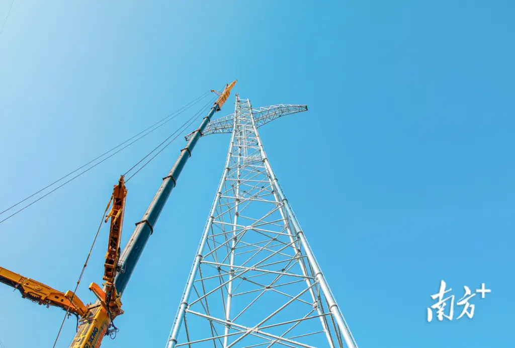
The process of fabrication involves splitting the complex three-dimensional structure into thousands of two-dimensional members. The only definitive technical mechanism to ensure that the assembly can be reversed perfectly at the remote site is the Trial Erection of the tower on the factory floor—a process that serves as the ultimate Quality Assurance (QA) gateway before the irreversible step of galvanization.
The Protocol of Trial Assembly
Trial erection is not a mere partial check; it is a full or near-full physical re-creation of the tower structure on the assembly bed.
-
Sampling Strategy: For standard, high-volume tangent towers ($110 \text{ kV}$), only a statistically significant sample (e.g., one in ten) might be trial assembled. However, for large, unique, and structurally critical towers—such as $750 \text{ kV}$ dead-end (tension) towers, prototype structures, or those with non-standard geometry—$100\%$ Trial Assembly is mandatory. This requirement acknowledges that the consequence of a dimensional error in a critical EHV structure is far too severe to risk.
-
The Assembly Process: The tower is assembled on a level, dimensionally controlled steel floor, using the actual production members. All connections are made using temporary pins or bolts. The purpose is to verify the geometric fit, ensuring all bolt holes align freely without the need for forced insertion (drifting), which indicates an unacceptable accumulation of tolerance errors. This process validates the entire upstream flow, from material cutting to bending and punching.
-
Critical Dimensional Checks: During trial assembly, key dimensional measurements are taken, including: the distance between foundation stubs (anchor points), the overall height, and, most crucially, the alignment of the cross-arm tips. These measurements are cross-referenced with the design drawings using calibrated tapes and laser measurement systems. Any dimensional error exceeding the specified tolerance requires the immediate identification and reprocessing of the faulty members before galvanization. A failure discovered after galvanization results in the costly, time-consuming necessity of stripping the zinc, correcting the dimension, and re-galvanizing, significantly impacting the project schedule and budget.
The trial erection, therefore, is the vital technical assurance step where the fabrication quality is structurally proven, validating the thousands of precise cuts and punches made during the automated process.
4. The Sentinel of Service Life: Hot-Dip Galvanization Science and QA
The final stage of tower manufacturing, the application of the corrosion protection system, is perhaps the most critical determinant of the structure’s long-term value and reliability. Since transmission towers are static assets exposed to the elements for decades, Hot-Dip Galvanization is the only accepted technological solution to provide the necessary sacrificial protection.
The Chemistry and Metallurgy of the Zinc Bond
The galvanization process is fundamentally a metallurgical reaction, not merely a coating application. It involves dipping the prepared steel members into a bath of molten zinc (maintained around $450^{\circ}\text{C}$).
-
Pre-Treatment: This chemical preparation is paramount. The members must be sequentially dipped into: a degreasing bath (to remove oils), an acid pickling bath (typically hydrochloric acid, to remove any residual iron oxide), and a fluxing bath (to chemically clean the surface and prepare it for the zinc bond). Failure at the pickling stage leaves scale or oxide, resulting in a bare spot (“uncoated area”) where zinc cannot alloy, leading to immediate field corrosion.
-
The Alloying Process: Once immersed in the molten zinc, the iron and zinc atoms diffuse, forming a series of highly durable zinc-iron alloy layers ($\Gamma, \delta, \zeta$) bonded strongly to the steel substrate, topped by a layer of pure zinc ($\eta$). This layered structure provides both a robust barrier and cathodic protection—the zinc preferentially sacrifices itself to protect the underlying steel when corrosion damage occurs.
Coating Thickness and Adhesion Assurance
The thickness of the zinc coating is directly correlated with the anticipated service life and is governed by material thickness and exposure environment (e.g., ISO 1461). For structural members, the minimum average coating thickness is often specified at $85 \mu\text{m}$ to $100 \mu\text{m}$.
-
Thickness Measurement: The final quality check involves non-destructive measurement of the coating thickness using a magnetic or electromagnetic gauge at multiple points on every critical member. Documentation of coating thickness must meet the specified minimum requirements.
-
Adhesion and Uniformity: The coating must be visually inspected for uniformity, and adhesion must be tested using methods such as the chisel and hammer test to ensure the metallurgical bond is sound and the coating will not flake or peel under mechanical stress during transport and erection.
The entire manufacturing process, from the selection of certified steel for $750 \text{ kV}$ towers to the final chemical bath, is an interconnected chain of engineering decisions aimed at transforming a geometric blueprint into a structurally precise, corrosion-resistant asset, ready to stand against the forces of nature for the lifespan of the electrical grid.
The Unseen Chain of Assurance: Integrated Quality Management and Traceability in Tower Fabrication
The manufacturing excellence achieved during the fabrication of overhead transmission line towers, particularly those robust lattice structures engineered for the extreme mechanical and electrical demands of the $500 \text{ kV}$ to $750 \text{ kV}$ systems, is rendered incomplete and indeed, technically invalid, without an overarching, meticulously documented system of Integrated Quality Management and Traceability. This administrative and technical framework serves as the definitive bridge between the designer’s mathematical model and the physical reality of the assembled structure, ensuring that every piece of steel, from the primary leg member to the smallest gusset plate, carries an auditable history of its metallurgical properties, dimensional accuracy, and corrosion protection status. The system is predicated on the principle that, given the non-redundant criticality of high-voltage transmission assets, an error in material substitution or an undocumented variance in galvanization thickness constitutes an unacceptable risk to grid reliability and public safety, demanding a level of documentation transparency that far surpasses standard construction material practices.
1. The Audit Trail: Material Traceability and Certification
The journey of every structural tower member begins with the integrity of its Mill Test Certificate (MTC), often referred to as a $3.1$ or $3.2$ certification under EN 10204 standards, which provides the immutable record of the steel’s chemical composition and mechanical properties (yield strength, tensile strength, elongation). The manufacturing facility must implement a robust procedure to ensure that the physical steel delivered to the shop floor matches the MTC, and, crucially, that this traceability is maintained throughout the entire cutting, punching, and galvanizing cycle.
Heat Lot Identification and Permanent Marking
The critical process for maintaining this link is Heat Lot Identification. The raw steel, sourced from a specific casting or ‘heat’ at the steel mill, is marked with a unique code. This code must then be transferred onto every individual piece cut from the stock material before any fabrication process commences. Modern fabrication lines integrate automated stamping, etching, or low-stress marking systems into the CNC punching process, permanently engraving the member identification number and the Heat Lot code directly onto the steel surface. This step is non-negotiable, particularly for the main members of UHV towers where the required steel grade (e.g., Q345/Grade 50) is vital for structural integrity. If a structural member were to fail during service due to unforeseen material defect, this permanent marking allows investigators to trace the failure directly back to the specific heat lot, the original MTC, and the precise batch testing performed at the mill, providing the essential legal and engineering audit trail. The integrity of the marking must also be resistant to the harsh chemical environment of the hot-dip galvanizing process, ensuring the identification remains readable on the finished, zinc-coated piece.
Document Control and the Quality Plan
The technical manufacturing guide is embodied within the Quality Control Plan (QCP), a document detailing every check point, tolerance limit, and corrective action required throughout the fabrication lifecycle. The QCP specifies the frequency of gauge calibration (for CNC machines), the required tolerance on bolt hole diameter ($\pm 0.1 \text{ mm}$ typically), and the minimum acceptable zinc coating thickness ($85 \mu\text{m}$ for many structural members). This formalized documentation ensures that quality checks are not discretionary but mandatory, providing objective evidence that the structure was built precisely according to the design specifications. This documentation is the final product delivered to the client, serving as the necessary proof of compliance for regulatory bodies and essential for long-term asset management and maintenance planning.
2. The Failure Prevention Paradigm: Economics of Precision
The intense focus on dimensional precision during fabrication is driven by a fundamental economic and logistical reality: the cost of correcting an error in the field exponentially exceeds the cost of correcting the same error in the factory. This paradigm dictates the necessity of the rigorous trial erection and zero-tolerance policies on dimensional errors for high-voltage towers.
The Cost Penalty of Field Rework
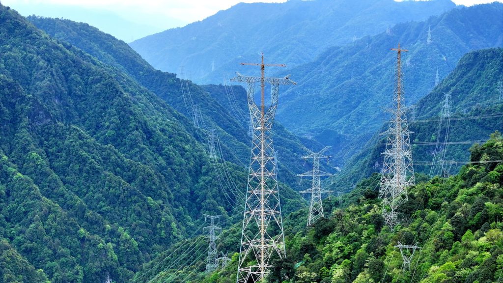
A structural member arriving at a remote construction site (perhaps in mountainous or inaccessible terrain) that does not align with its mating member—a misalignment of just a few millimeters due to cumulative punching errors—requires immediate and costly intervention. The options for correction are universally detrimental:
-
Reaming/Drifting: Forcing the members into alignment by physically expanding the hole diameter (reaming) or driving a tapered steel pin (drifting). This operation compromises the material around the bolt hole, introducing stress risers, reducing the friction grip potential, and potentially invalidating the structural design strength—a non-permissible solution for primary members of a $750 \text{ kV}$ tower.
-
Rework/Replacement: Dismantling the assembly, transporting the misaligned piece back to a secondary workshop (if available), stripping the galvanization, correcting the hole, re-galvanizing, and shipping the member back to the site. This process introduces weeks of delay, massive logistical expense, and increases the potential for further error and surface damage.
The commitment to CNC automation and the meticulous, labor-intensive trial assembly process in the factory is, therefore, a massive investment in failure prevention. It is the cheapest, most efficient stage to catch and correct the inevitable geometric variances inherent in transforming flexible steel raw material into a rigid structural assembly. This economic imperative justifies the capital expenditure on high-precision fabrication equipment and the overhead of a dedicated QA team to ensure perfect fit before the galvanizing process locks in any dimensional flaws.
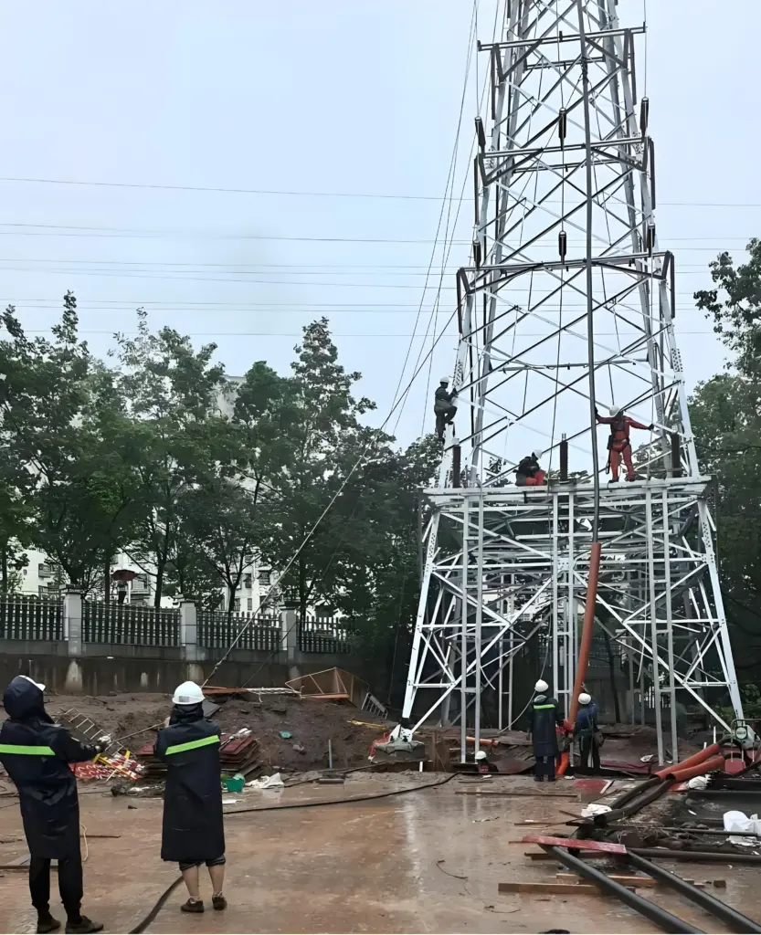
3. Packaging, Handling, and Logistics: The Final Factory Gate
The structural integrity and long-term durability of the fabricated tower components must be preserved through the arduous final phase: packaging, handling, and transportation to the construction site, which may be thousands of kilometers away and often accessed only by temporary roads.
Bundling Strategy and Sequential Labeling
The vast number of unique members in a single tower assembly necessitates a highly sophisticated packaging and bundling strategy. Members must be grouped, or bundled, not randomly, but according to specific criteria to facilitate easy identification, inventory, and field erection sequencing:
-
Weight and Size Grouping: Heavy members (main legs, base plates) are grouped separately from lighter bracing members to ensure safe handling and optimized loading of transport vehicles.
-
Erection Sequence Grouping: For highly organized projects, members may be bundled based on their erection sequence—the pieces required for the first section of the tower are grouped together, separate from the pieces for the peak. This minimizes time wasted searching through piles of steel at the base of the tower during the erection process.
-
Corrosion Prevention during Transit: The bundles must be secured using galvanized steel strapping and often protected with plastic film or temporary protective coatings at points where the strapping might cause abrasion to the zinc finish. Furthermore, the bolts, nuts, and washers—which are highly susceptible to corrosion and theft—are meticulously counted, coated in light anti-corrosion oil, and sealed in robust, clearly labeled wooden crates or steel barrels.
Documentation and Inventory Control
Every single bundle must be clearly and permanently labeled with a weatherproof tag indicating the tower number, the assembly section (e.g., Body Section B, Cross-Arm Left), and a list of the contents. This crucial field-level documentation allows the site management team to quickly and accurately reconcile the physical steel delivered against the shipping manifest and the Component List, serving as the final factory gate assurance that the full structural material requirements have been met. Any discrepancy at this stage (e.g., missing critical members) triggers immediate factory action, avoiding a work stoppage once the expensive lifting equipment and specialized erection crews are mobilized on site.
4. Future Trends: Automation and Digitalization in Fabrication
Looking forward, the fabrication of $750 \text{ kV}$ and future UHV towers will increasingly rely on advanced technological integration to manage the ever-increasing demands for size, precision, and efficiency.
Robotic Welding and Digital Twin Verification
The shift towards highly complex, multi-planar connections (nodes) for extreme loading conditions requires techniques beyond simple bolting, often involving heavy plate welding. Future fabrication will see the greater adoption of Robotic Welding Systems to achieve consistently high-quality, high-penetration welds that minimize residual stress and maximize structural reliability—a level of consistency unattainable with manual welding. Furthermore, the entire fabrication process is moving towards Digital Twin Verification, where the precise measurements taken during the factory’s trial assembly (using 3D laser scanners) are immediately compared against the original digital design model, providing instant, highly accurate feedback on geometric compliance and eliminating the reliance on manual tape measurements. This digital feedback loop ensures that the fabrication of tomorrow’s ultra-massive towers meets sub-millimeter precision, guaranteeing the structural integrity required for the next generation of high-capacity transmission corridors.