
Wind Load Resistance in Self-Supporting Lattice Transmission Towers
Global Transmission Line Tower Industry Technical Analysis
December 16, 2025330kV Electric Transmission Line Tower
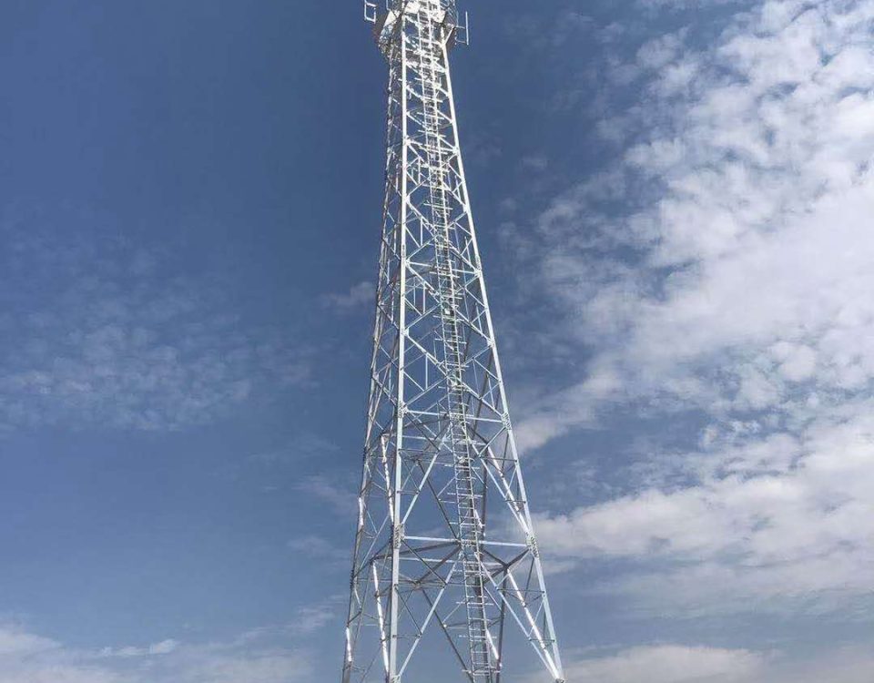
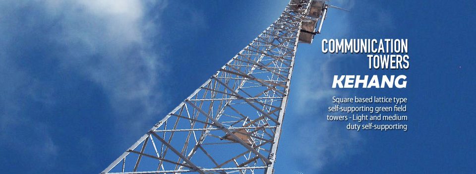
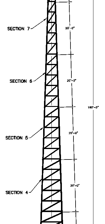
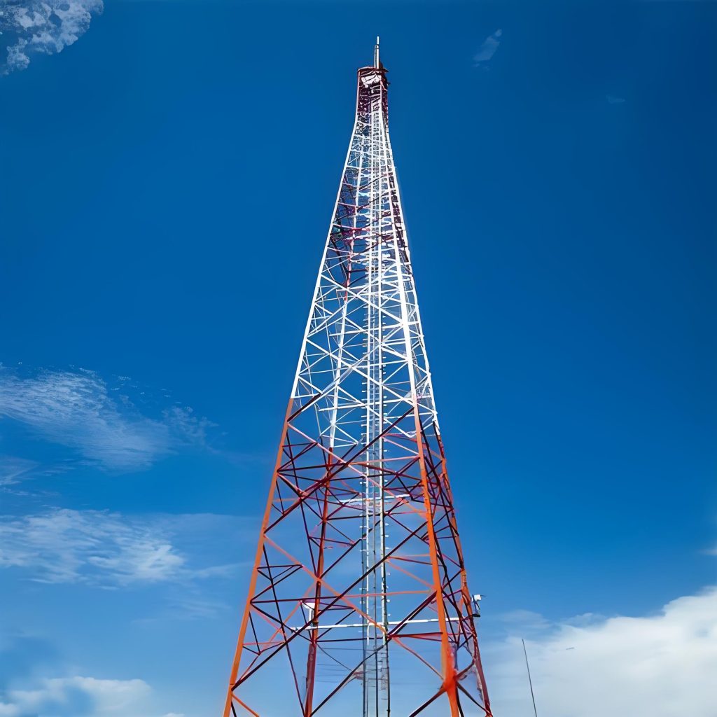
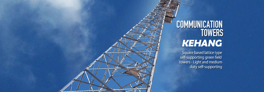
January 1, 2026When we conceive of a Self-Supporting Lattice Transmission Towers, we are not merely discussing an assembly of galvanized steel; we are contemplating a masterpiece of spatial efficiency and autonomous structural integrity. These towers are the silent, skeletal sentinels of the modern world, engineered to stand entirely on their own strength without the aid of guy wires, drawing their stability from a wide, rigid base and a meticulously calculated geometric hierarchy. To understand this product is to enter a world where the chaotic, non-linear forces of nature—the violent thrust of a 100-year storm, the crushing weight of radial ice, and the rhythmic oscillations of conductor galloping—are systematically deconstructed and neutralized through the elegant logic of truss mechanics. The “self-supporting” philosophy is rooted in the realization that in the world’s most unforgiving environments—mountainous peaks, corrosive coastlines, and remote wilderness—simplicity in installation must be matched by complexity in engineering. Each member of our tower is a vital link in a load-sharing network, where high-strength steel angles are positioned to maximize the moment of inertia while minimizing the wind-catch area, creating a structure that is paradoxically both incredibly light and nearly indestructible.
The genetic blueprint of our towers begins in the furnace, where the chemical composition of the steel is forged to meet the exact demands of structural resilience. We utilize high-strength structural steels like Q355, Q420, and Q460, which are not merely chosen for their yield points but for their metallurgical balance. We understand that carbon provides the necessary strength, but it must be tempered by manganese to ensure deep hardenability, while silicon acts as a vital deoxidizer to maintain internal purity. The following table outlines the rigorous chemical standards we maintain to ensure that our towers possess the uniform crystalline structure required to resist the unpredictable shear and axial stresses of extreme climate events.
Table 1: Chemical Composition (Standard Grade Reference)
| Element | Carbon (C) max % | Silicon (Si) max % | Manganese (Mn) % | Phosphorus (P) max % | Sulfur (S) max % |
| Grade Q355B | 0.20 | 0.50 | 1.00 – 1.60 | 0.035 | 0.035 |
| Grade Q420B | 0.20 | 0.50 | 1.00 – 1.70 | 0.030 | 0.030 |
| Grade Q460C | 0.20 | 0.60 | 1.00 – 1.80 | 0.030 | 0.025 |
Beyond chemistry, the life of a tower member is defined by its thermal history. Our heat treatment processes are designed to refine the grain size of the steel, moving past the raw rolling state into a homogenized condition that eliminates residual stresses. This is crucial for the heavy-duty “leg members” which anchor the structure to the foundation. Without proper normalization and stress relief, the sudden application of dynamic wind loads could trigger micro-cracking at bolt holes. By carefully controlling the cooling rates and the tempering windows, we ensure that the steel remains ductile even in sub-zero temperatures, preventing the catastrophic brittle fractures that have historically plagued lesser structures in arctic or high-altitude deployments.
Table 2: Heat Treatment & Processing Protocols
| Process Stage | Parameters | Engineering Objective |
| Normalizing | 880°C – 920°C | Homogenize grain structure and improve toughness. |
| Stress Relieving | Post-Welding/Heavy Forming | Eliminate internal tension to prevent warping during galvanizing. |
| Hot-Dip Galvanizing | 445°C – 460°C | Create a thick, metallurgical zinc-iron alloy for 50-year corrosion life. |
The mechanical performance of our self-supporting towers is defined by a triad of metrics: Yield Strength, Tensile Strength, and Elongation. In a wind-loading scenario, the tower acts as a massive vertical cantilever. The windward legs are stretched in intense tension, while the leeward legs must resist massive compressive buckling forces. Our product is designed with a “Reserve Capacity” factor that ensures the tower remains within the elastic range even under 120% of the design wind speed. This ductility—the ability of the steel to deform slightly without failing—is what allows our towers to absorb the kinetic energy of gusting winds rather than snapping under the pressure.
Table 3: Tensile & Mechanical Requirements
| Property | Value (Grade Q355) | Value (Grade Q420) | Value (Grade Q460) |
| Yield Strength ($R_{eH}$) | $\ge 355$ MPa | $\ge 420$ MPa | $\ge 460$ MPa |
| Tensile Strength ($R_m$) | 470 – 630 MPa | 520 – 680 MPa | 550 – 720 MPa |
| Elongation ($A_5$) | $\ge 21\%$ | $\ge 19\%$ | $\ge 17\%$ |
| Impact Energy (KV2) | 27J (at -20°C) | 34J (at -20°C) | 40J (at -20°C) |
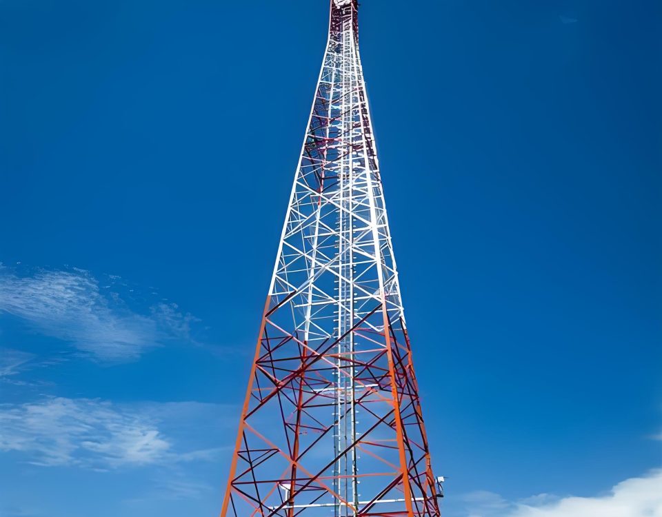
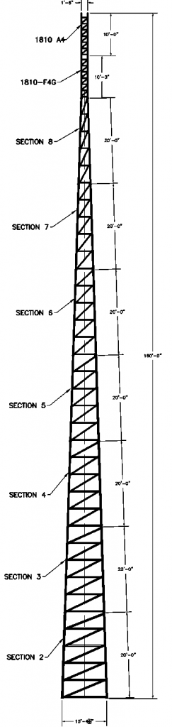
The true brilliance of our tower design lies in its Aero-Structural Optimization. Every bracing pattern—whether it is the classic X-brace for high torsional rigidity or the K-brace for localized buckling resistance—is selected based on a Finite Element Analysis (FEA) that simulates thousands of load cases. We don’t just design for static weight; we design for the “Unbalanced Longitudinal Load,” simulating the sudden snap of a conductor wire to ensure the tower doesn’t experience a progressive collapse. The tower’s silhouette is a response to the “Power Law” of wind speed, tapering gracefully as it rises to minimize the lever arm of the wind at higher altitudes.
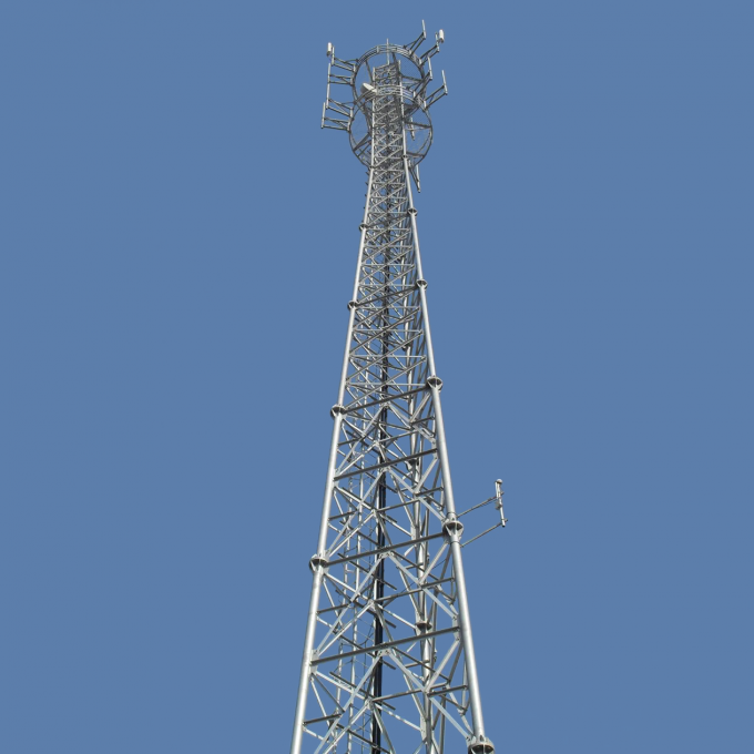
Our Self-Supporting Lattice Towers are not just products; they are high-performance engineering assets. Every bolt hole is precision-punched or drilled to ensure perfect alignment during field assembly, reducing labor costs and preventing the introduction of “fit-up stresses.” We treat corrosion protection as a core structural requirement, utilizing high-purity zinc in our galvanizing baths to exceed ISO 1461 standards, ensuring that the structural integrity of the steel is protected for decades. When you choose our towers, you are investing in a product that combines the legacy of time-tested lattice geometry with the cutting-edge metallurgical science of the 21st century—a structure built to endure, to protect, and to empower.
Would you like me to focus on a specific voltage level (e.g., 500kV vs 110kV) for the technical load cases, or perhaps generate a detailed installation and maintenance guide section?
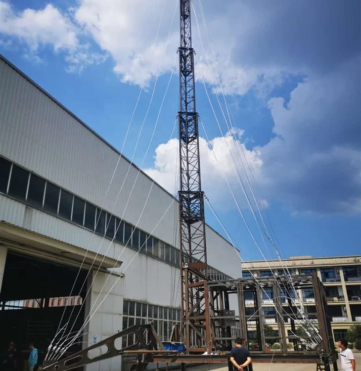
When we step into the specialized domain of structural engineering, specifically the mechanics governing self-supporting lattice transmission towers, we find ourselves at a peculiar intersection of Euler-Bernoulli beam theory and the chaotic, non-linear reality of atmospheric boundary layer physics. These towers, those skeletal sentinels that march across the topography of our modern civilization, are not merely static steel frames; they are dynamic filters of kinetic energy, constantly translating the invisible force of the wind into internal axial stresses and complex vibration modes. To truly analyze the wind resistance of a self-supporting transmission tower, we must first abandon the comforting simplicity of static equivalent loads and delve into the stochastic nature of the wind itself, recognizing that wind is not a steady pressure but a turbulent fluid flow characterized by varying intensity, scale, and frequency. This internal monologue of engineering logic begins with the fundamental realization that the tower’s resistance is a delicate balance between its geometric configuration—the specific bracing patterns like K-bracing, X-bracing, or Warren types—and the material properties of high-strength structural steel, often Grade Q355 or Q420, which must withstand massive compressive and tensile forces without buckling or yielding under the extreme peak gusts of a 50-year or 100-year return period storm.
The analytical journey starts with the definition of the wind field, which is a complex tapestry of mean wind speed profiles and fluctuating components. We apply the power law or logarithmic law to describe how wind velocity increases with height, a phenomenon driven by ground roughness, but this is only the macroscopic view; the real danger lies in the gust factor and the spatial correlation of turbulence. As the wind flows through the lattice members, it doesn’t just push; it creates a drag force that is highly dependent on the solidity ratio of the tower sections. We must meticulously calculate the drag coefficients ($C_d$) for various angles of attack, acknowledging that a lattice tower’s projected area changes as the wind shifts, sometimes creating a “shielding effect” where leeward members are partially protected by windward ones, though this protection is often illusory in highly turbulent flows. The complexity deepens when we consider the interaction between the tower and the conductors. The conductors, with their massive spans and sag geometries, act as giant sails, capturing wind energy and transmitting it to the tower cross-arms as concentrated point loads. This coupling means the tower’s wind resistance isn’t just about the steel structure itself but about the entire mechanical system, including the aeroelastic behavior of the cables, which can undergo galloping or Aeolian vibrations, further taxing the structural integrity of the tower’s upper segments.
Moving deeper into the structural response, we transition from the load side to the resistance side through the lens of Finite Element Analysis (FEA). In a sophisticated technical analysis, we cannot rely on simple truss assumptions where every member is pinned; we must account for the semi-rigid nature of bolted connections and the secondary stresses induced by the eccentricity of the joints. The “self-supporting” nature of these towers means they rely entirely on their wide base and the moment-resisting capacity of their foundations to prevent overturning. Here, we encounter the critical phenomenon of member buckling. Since lattice towers are primarily comprised of angle steel, we face the challenge of thin-walled section instability. When a hurricane-force wind strikes, the windward legs are thrown into intense tension—often a manageable state for steel—but the leeward legs are subjected to massive compression. The resistance analysis then becomes a battle against the slenderness ratio. We must evaluate the effective length of each member, considering how the bracing points provide lateral restraint. If the slenderness ratio is too high, the member will buckle globally; if the width-to-thickness ratio of the angle leg is too high, it will buckle locally. The holistic strength of the tower is only as robust as its weakest localized connection or its most slender diagonal brace, creating a systemic vulnerability that requires a non-linear buckling analysis (often using the Riks method or similar incremental-iterative solvers) to find the true ultimate limit state beyond the initial elastic threshold.
The temporal dimension of wind resistance adds another layer of sophistication: the dynamic response. Every self-supporting tower has a set of natural frequencies and mode shapes. If the power spectral density of the wind turbulence contains significant energy at frequencies that coincide with the tower’s fundamental natural frequency—usually between 0.5 Hz and 2.0 Hz—the structure will experience resonance. This dynamic amplification can lead to stresses far exceeding those predicted by static calculations. We utilize the Davenport spectrum or the Kaimal spectrum to model this turbulence, performing a frequency-domain analysis to determine the “Gust Response Factor.” However, in modern high-fidelity simulations, we often move toward time-history analysis, where we generate synthetic wind speed time series and “shake” the digital twin of the tower to observe its real-time displacement and stress evolution. This allows us to see the “breathing” of the tower and the fatigue accumulation in the bolted joints. The bolts themselves are a critical, often overlooked, component of wind resistance; the shear and bearing capacities of the bolt groups must be sufficient to transfer the cumulative wind shear from the top of the tower down to the leg extensions, where the force is finally dissipated into the reinforced concrete pile or pad foundations.
Furthermore, we must address the geographic and environmental context of the analysis. A tower designed for the plains of the Midwest faces different wind profiles than one situated on a mountain ridge or a coastal cliff. In mountainous terrain, the “speed-up effect” or “topographic multiplier” can accelerate wind speeds significantly as the air is compressed over a ridge, a factor that can lead to catastrophic failure if not properly accounted for in the initial site-specific wind climate assessment. We also have to consider the directionality of the wind. Most towers are designed with a degree of symmetry, but the most critical loading cases often occur when the wind hits at a 45-degree angle to the tower face, maximizing the load on specific leg members. The synergy of wind and ice—ice accretion—also complicates the resistance analysis. Even a thin layer of ice increases the surface area (drag) and the mass (inertia) of the members and conductors, fundamentally changing the tower’s dynamic signature and making it more susceptible to wind-induced oscillations. This multi-hazard environment requires a probabilistic approach to safety, using Load and Resistance Factor Design (LRFD) to ensure that the probability of failure remains acceptably low over the intended 50-year lifespan of the asset.
In the final synthesis of a technical wind resistance analysis, we look toward the future of structural health monitoring and mitigation strategies. To enhance the resistance of existing towers, engineers might employ tuned mass dampers (TMDs) to absorb vibrational energy or implement structural reinforcement such as adding “diaphragms” at critical heights to maintain the cross-sectional shape under torsion. The advent of High-Performance Computing (HPC) allows us to run thousands of Monte Carlo simulations, varying the wind speed, direction, and material strength to create a fragility curve for the tower. This curve provides a sophisticated statistical map of risk, showing that while a tower might withstand a 40 m/s wind with 95% confidence, its probability of failure might climb exponentially at 50 m/s. This level of depth moves the conversation beyond “will it stand?” to “how will it fail, and what is the margin of safety?” It is this rigorous, multi-physics approach—integrating fluid dynamics, structural mechanics, and statistical probability—that defines the pinnacle of modern transmission tower engineering.
The pursuit of a comprehensive understanding of wind resistance in self-supporting transmission towers necessitates an even deeper dive into the granular mechanics of the atmospheric boundary layer and its interaction with the lattice topology. When we talk about the “wind,” we are essentially discussing a multi-scale energy cascade, where large-scale synoptic flows break down into smaller, high-frequency eddies. For a tower, which is a slender, high-aspect-ratio structure, the spatial correlation of these eddies is the silent determinant of structural survival. If a gust is small in physical dimensions—smaller than the width of the tower—it might only buffet a single bracing member. However, if the gust is large enough to encompass the entire span of the cross-arms and the attached conductors, the resulting coherent pressure wave can induce a global moment that tests the very limits of the foundation’s pull-out resistance. This leads us to the critical evaluation of the “size effect” in wind engineering. We must utilize the coherence function, which mathematically describes how the wind speed at one point on the tower relates to the wind speed at another point. If the coherence is high across the height of the tower, the structure experiences a synchronized “shove,” which is far more taxing on the main leg members than a disorganized, turbulent flow.
This brings us to the fascinating and terrifying world of aeroelasticity, specifically the phenomenon of “galloping” and its impact on tower resistance. While we often analyze the tower as a standalone steel entity, it is inextricably linked to the conductors. In conditions of freezing rain, asymmetrical ice shapes form on the cables, turning a simple cylinder into an unstable airfoil. When the wind hits these iced conductors, it creates aerodynamic lift that can lead to high-amplitude, low-frequency oscillations. The tower, in this scenario, is no longer just resisting a horizontal wind pressure; it is being subjected to massive, rhythmic vertical and longitudinal “yanking” forces. A technical analysis must therefore account for the longitudinal load-sharing capabilities of the tower. If one span of conductors fails or experiences extreme galloping, the self-supporting tower must be robust enough to withstand the resulting unbalanced tension. This is why the “broken wire” condition is often a governing load case in the design of these structures, acting as a proxy for the extreme dynamic transients induced by wind-related cable failures. We analyze this using non-linear cable elements in our finite element models, accounting for the catenary geometry and the sudden release of potential energy that occurs during a conductor break.
Beneath the macro-stresses of the tower frame lies the microscopic reality of the bolted joints, which are the true “Achilles’ heel” of wind resistance. In a self-supporting tower, thousands of bolts act as the primary mechanism for force transfer. Under high-velocity winds, these joints are subjected to cyclic loading that can lead to “bolt slip.” When a bolt slips, the geometry of the tower subtly shifts, redistributing internal stresses in ways that the original linear elastic model might not predict. A deep-dive analysis must incorporate the friction-grip behavior of these connections. If the wind load exceeds the frictional resistance between the galvanized steel plys, the joint moves into a bearing state, where the bolt shank presses directly against the edge of the hole. This transition causes a momentary drop in the local stiffness of the tower, which can alter its natural frequency and potentially move it closer to a resonance band with the wind’s turbulence. To combat this, high-strength friction-grip bolts (such as ASTM A325 or equivalent) are often specified, and the analysis must verify that the “slip-critical” capacity is not exceeded under the serviceability limit state, while ensuring the ultimate bearing capacity holds firm during a catastrophic gust.
Furthermore, we must scrutinize the “P-Delta” effect, a second-order geometric non-linearity that becomes increasingly significant as the tower height grows. As the wind pushes the tower, it deflects. Once the tower is in a deflected shape, the gravity loads (the weight of the steel, insulators, and conductors) are no longer aligned with the original vertical axis of the legs. This eccentricity creates additional “secondary” moments. In a 60-meter or 100-meter tower, these P-Delta effects can increase the base moment by 5% to 15%, a margin that can mean the difference between a stable structure and a localized collapse. To accurately model this, we must use an iterative structural solver that updates the stiffness matrix of the tower at every load increment, accounting for the “softening” of the structure as it leans into the wind. This is particularly crucial for the leeward legs, which are already fighting a losing battle against compression-induced buckling; the added P-Delta moment further eccentricities the axial load, accelerating the onset of Euler buckling in the main leg angles.
The material science aspect of the analysis also deserves a deep investigation, particularly the impact of low temperatures on the ductility of the steel. In many regions where high winds are prevalent—such as the arctic or high-altitude plateaus—the steel must maintain its toughness to prevent “brittle fracture” under the high-strain rates of a wind gust. If the steel’s transition temperature is higher than the ambient environment, a sudden gust could initiate a crack at a bolt hole or a weld, leading to a catastrophic “unzipping” of the tower. Thus, wind resistance analysis is not just a study of forces, but a study of fracture mechanics and material selection. We look for steels with high Charpy V-notch (CVN) impact values. In the context of a “product technical analysis,” this means the tower isn’t just a geometry; it is a carefully curated metallurgical assembly. The interaction between the zinc coating (galvanization) and the base steel must also be considered, as hydrogen embrittlement or “liquid metal embrittlement” during the dipping process could theoretically create micro-cracks that the wind will eventually exploit through fatigue.
Finally, we must consider the evolution of the “Design Wind Speed” itself in an era of shifting climatic patterns. Modern engineering is moving away from static historical maps toward more dynamic, “non-stationary” wind models. We are now seeing the integration of Computational Fluid Dynamics (CFD) with structural FEA to create “Fluid-Structure Interaction” (FSI) simulations. In an FSI model, the wind doesn’t just apply a force to the tower; the tower’s movement actually pushes back on the air, altering the flow field around it. This level of analysis is the “gold standard” for understanding vortex shedding—where alternating low-pressure zones form behind the members, causing the tower to vibrate perpendicular to the wind direction. While this is more common in tubular poles, lattice towers with dense bracing can also experience “buffeting” from vortex shedding of the individual members. By analyzing the “Strouhal number” ($St$) of the individual angles and the tower as a whole, we can ensure that the frequency of these shed vortices stays far away from the tower’s structural modes. This holistic, multi-disciplinary approach—spanning from the metallurgical grain structure of a bolt to the massive aeroelastic coupling of a 500-meter span of conductors—is what constitutes a truly rigorous analysis of self-supporting transmission tower wind resistance.