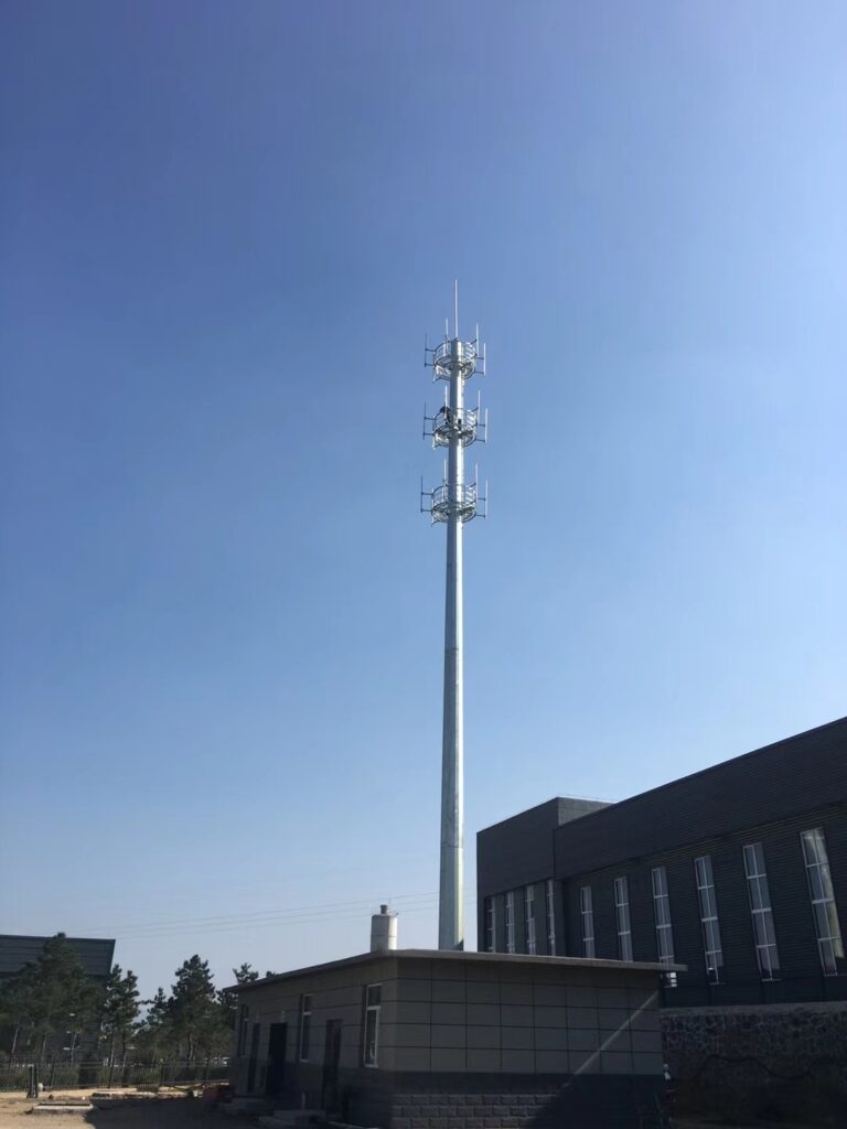
Communication Monopole Steel Tower – Seismic Performance Analysis
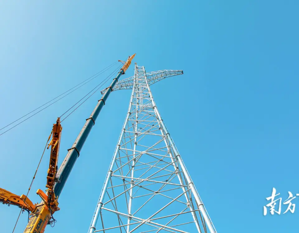
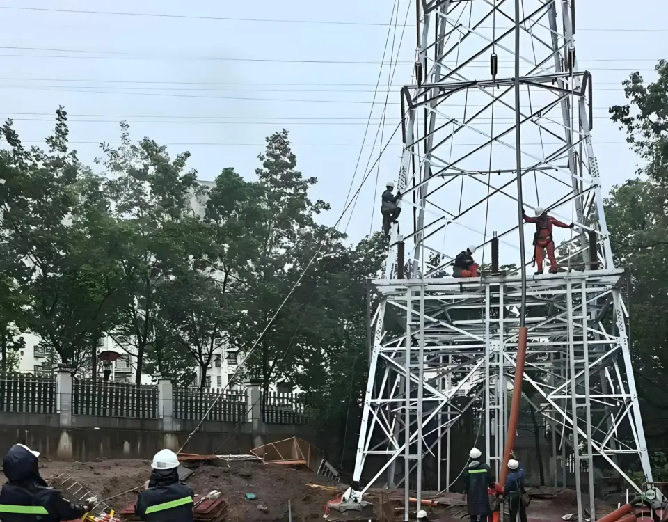
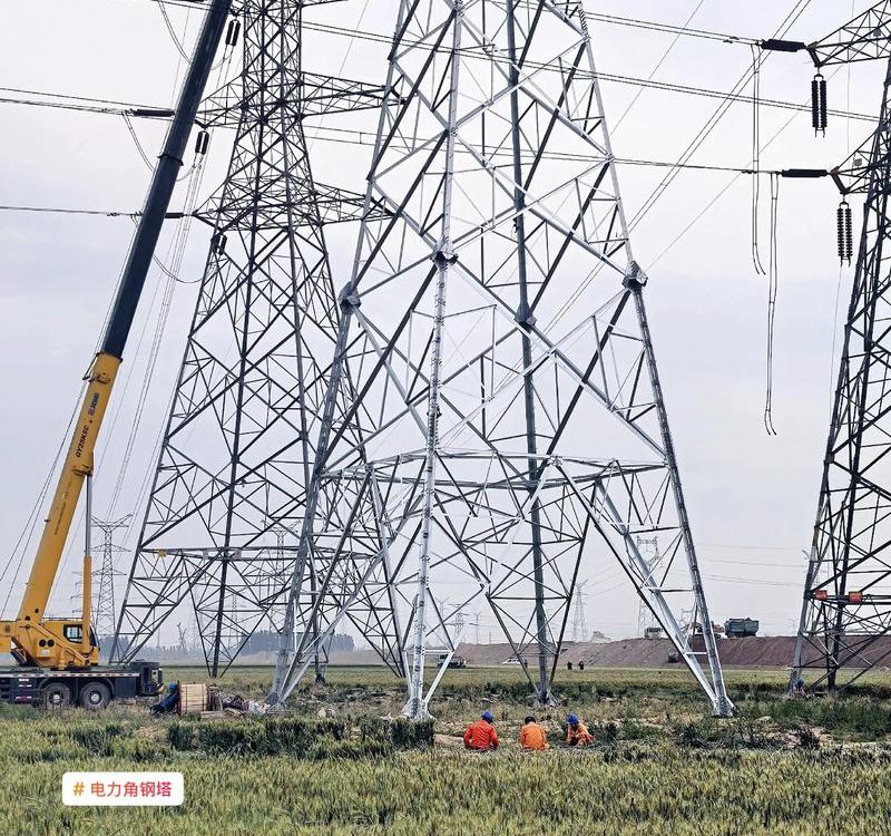
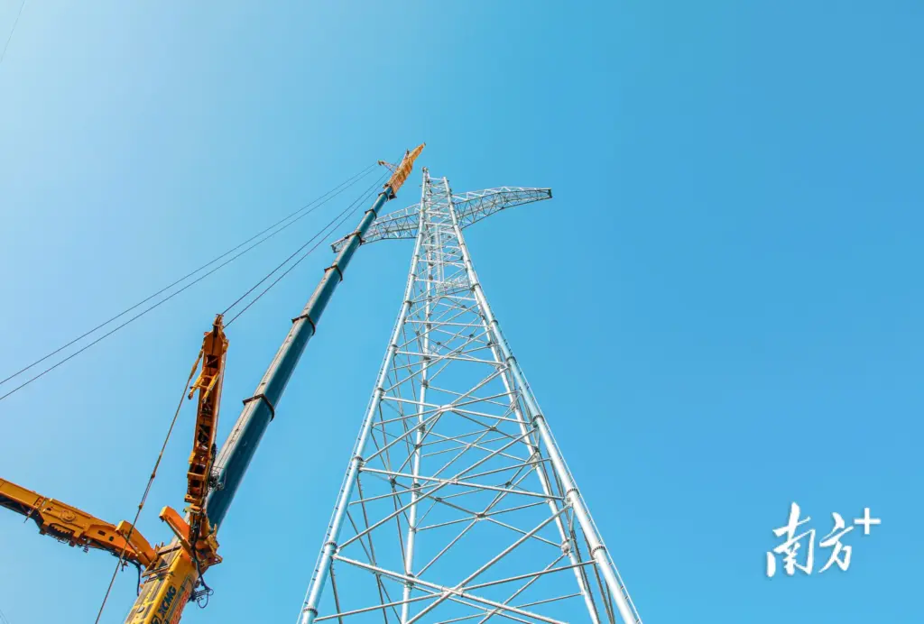
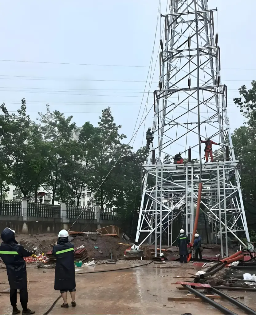
October 17, 2026Construction Technology for Erecting Steel Towers of Ultra-High-Voltage Transmission Lines
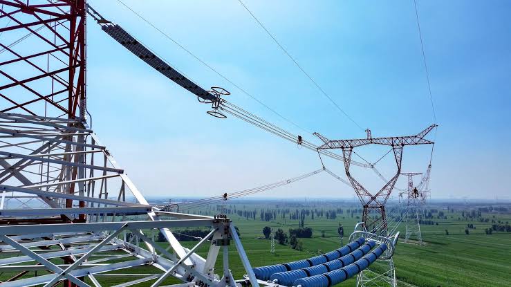
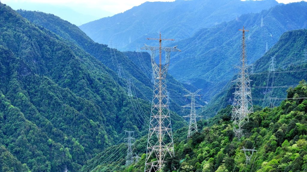
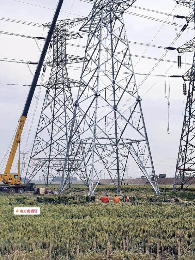
Construction Technology for Erecting Steel Towers of Ultra-High-Voltage (1000kV UHV) Transmission Lines
Comprehensive structural rigging data, gin-pole mechanical load parameters, luffing-jib tower crane erection matrices, and high-altitude hoisting tolerances for Cat-Head (Mao-Tou), Cup-Type (Jiu-Bei), and Dry-Type Tension (Gan-Zi) 1000kV steel lattice towers.
1. Structural & Mechanical Comparison: 1000kV UHV vs. 500kV EHV Steel Towers
TABLE 1 // BASELINE METRICSCompared with conventional 500kV extra-high-voltage (EHV) transmission towers, 1000kV ultra-high-voltage (UHV) lattice towers exhibit substantially increased nominal height, wider cross-arm spans, heavier single-member unit weights, and larger main leg profiles. Standard 500kV rigging equipment fails to meet axial buckling and overturning moment thresholds; specialized erection methodologies are required for Cat-Head, Cup-Type, and Dry-Type Tension structures.
| Comparison Parameter | Unit | 500kV EHV Standard Tower | 1000kV UHV Cat-Head Tower | 1000kV UHV Cup-Type Tower | 1000kV UHV Dry-Type Tension | UHV / 500kV Ratio |
|---|---|---|---|---|---|---|
| Nominal Height (Call Height) | m | 27.0 – 45.0 | 45.0 – 81.0 | 42.0 – 66.0 (Typ. 51.0) | 36.0 – 54.0 (Typ. 42.0) | 1.50x – 1.80x |
| Total Structural Height | m | 38.0 – 58.0 | 67.0 – 103.0 | 52.0 – 78.0 (Typ. 59.0) | 58.0 – 75.0 (Typ. 68.3) | 1.65x – 1.90x |
| Single Tower Total Weight | t | 18.0 – 38.0 | 41.0 – 104.0 (Avg. 56.0) | 48.0 – 72.0 (Typ. 54.0) | 85.0 – 195.0 (Typ. 93.5) | 2.20x – 5.10x |
| Max Cross-Arm Span | m | 14.0 – 24.0 | 23.0 (Middle Cross-Arm) | 50.7 (Full Span) | 16.0 – 31.0 (Single Side) | 1.85x – 2.15x |
| Base Root Opening (Footprint) | m | 6.5 – 10.5 | 11.5 – 18.2 | 10.8 – 15.6 | 14.2 – 21.5 | 1.75x – 2.05x |
| Main Leg Angle Steel Spec | mm | ∠140×12 – ∠180×16 | ∠200×18 – ∠250×24 | ∠200×20 – ∠250×26 | ∠250×28 – Double ∠250×32 | 2.40x Section Area |
| Single Member Max Weight | kg | 280 – 550 | 950 – 1,680 | 1,100 – 1,850 | 1,650 – 3,200 | 3.20x – 5.80x |
| Primary Erection Rigging | Type | 500×500mm Inner Gin Pole | 900×900×40000mm Gin Pole | 750×750mm Hybrid / Dual 650mm | 750×750mm / Luffing Tower Crane | Heavy-Duty Upgrade |
1.2 Structural Material Specifications: Chemical Composition & Mechanical Properties
METALLURGICAL ARCHIVE // Q345, Q420, 6061-T6UHV transmission towers and suspension gin poles utilize high-strength low-alloy (HSLA) structural steels (Q345B, Q420B) alongside aerospace-grade extruded aluminum alloys (6061-T6 / 7A04-T6) to maximize strength-to-weight ratios during high-altitude lifting.
| Material Grade | UNS / Std | C (%) | Si (%) | Mn (%) | P (%) | S (%) | Alloying Elements |
|---|---|---|---|---|---|---|---|
| Q345B (Gin Pole / Body) | GB/T 1591 | ≤ 0.20 | ≤ 0.50 | ≤ 1.70 | ≤ 0.035 | ≤ 0.035 | V: 0.02–0.15; Nb: 0.015–0.06 |
| Q420B (Tower Main Legs) | GB/T 1591 | ≤ 0.20 | ≤ 0.50 | ≤ 1.70 | ≤ 0.030 | ≤ 0.030 | Ti: 0.02–0.20; Cr ≤ 0.30 |
| 6061-T6 (Al Gin Pole) | UNS A96061 | — | 0.40–0.80 | ≤ 0.15 | — | — | Mg: 0.8–1.2; Cu: 0.15–0.40 |
| 7A04-T6 (High-Load Al) | GB/T 3190 | — | ≤ 0.50 | 0.20–0.60 | — | — | Zn: 5.0–7.0; Mg: 1.8–2.8 |
| Material Grade | Yield Strength (MPa) | Tensile Strength (MPa) | Elongation (%) | Density (g/cm³) | Elastic Modulus (GPa) |
|---|---|---|---|---|---|
| Q345B Steel (≤16mm) | ≥ 345 | 470 – 630 | ≥ 21% | 7.85 | 206 |
| Q420B Steel (≤16mm) | ≥ 420 | 520 – 680 | ≥ 19% | 7.85 | 206 |
| 6061-T6 Aluminum | ≥ 240 | ≥ 260 | ≥ 10% | 2.70 | 68.9 |
| 7A04-T6 Aluminum | ≥ 450 | ≥ 530 | ≥ 7% | 2.85 | 71.0 |
2. Erecting Cat-Head Towers Using a 900mm × 900mm × 40000mm Steel Gin Pole
2.1 Cat-Head Tower Dimensional & Mass Profile
TABLE 2| Structural Item | Unit | Cat-Head Tower Value | Erection Classification |
|---|---|---|---|
| Nominal Height (Call Height) | m | 45 – 81 | Variable Leg Extensions |
| Total Overall Height | m | 67 – 103 | Requires 40m Gin Pole |
| Total Tower Mass Range | t | 41 – 104 | Heavy Suspension Class |
| Average Tower Mass | t | 56 | Standard Line Tangent |
| Middle Cross-Arm Length / Mass | m / t | 23 / (3.9 – 5.7) | Segmented / Panel Hoist |
| Upper + Middle + Lower Crank Arm H / M | m / t | 23 / (5.7 – 7.3) | Combined Head Assembly |
| Upper + Middle Crank Arm Height / Mass | m / t | 13 / (1.6 – 2.0) | Single-Side Integrated Hoist |
| Lower Crank Arm Height / Single Mass | m / t | 10 / (4.1 – 5.3) | Front/Rear Panel Split |
2.2 900×900×40000mm Gin Pole Parameters & Limits
SPEC SHEET 2B| Parameter / Operating Condition | Specification / Threshold | Control Requirement |
|---|---|---|
| Gin Pole Nominal Dimension | 900mm × 900mm × 40,000mm | Lattice Box Section |
| Straight / Tapered Cross-Section | 900×900mm / 350×350mm | Upper & Lower Tapered Ends |
| Sectional Composition (40.0m) | (2.5m×12) + (2.0m×2) + (3.0m×2) | 34m Straight + 6m Tapered |
| Chord & Bracing Angle Profiles | Main: ∠90×90×8 | Brace: ∠50×50×4 | Structural Steel Q345 |
| Allowable Axial Compressive Force | 418 kN | Safety Factor K ≥ 2.5 |
| Max Allowable Lifting Load | 9.0 t (88.2 kN) | Strict Overload Prohibition |
| Outer Guy Wire / Tagline Ground Angle | ≤ 45° to Horizontal Ground | Minimizes Guy Tension |
| Hoist Rope Angle & Clearance | Rope ≤ 15° | Clearance ≤ 0.5m | Prevents Tower Collision |
| Support Rope / Gin Pole Tilt Angle | Support ≤ 30° | Pole Tilt ≤ 10° | 4-Point Equalized Support |
2.3 & 2.4 Cat-Head Tower Operational Rigging & Tower-Head Hoisting Matrix
TABLE 3 // CAT-HEAD RIGGING & HEAD ASSEMBLY| Operational Phase | Rigging & Hardware Setup | Technical Control & Safety Criteria |
|---|---|---|
| 1. Basic Rigging Setup | 2-2 Pulley Block (4 working falls, 5.4t rated); 100kN webbing slings (lower guys); φ15mm steel wire rope (upper guys). | Pre-tension all four guy lines symmetrically prior to initial load transfer. |
| 2. Initial Gin Pole Erection | 500mm × 500mm × 19m A-Frame (Ren-Zi) Gin Pole utilizing a 2-point lifting bridle. | Erect entire 40m gin pole vertically within assembled base tower legs; install dual waist rings immediately. |
| 3. Gin Pole Jumping (Lifting) | Diagonal main leg chords as anchor points; 4 working hoist falls lifting simultaneously. | Maintain at least 2 active waist rings throughout climbing to enforce strict verticality and reduce eccentric bending. |
| 4. Tower Panel Hoisting | Steel pipe stiffeners lashed across wide lattice panels; dual taglines on outer panel corners. | Gin pole tilt ≤ 10°; maintain horizontal clearance ≤ 0.5m between lifted panel and tower body. |
| 5. Gin Pole Dismantling | 4 upper guy lines + 4 working hoist ropes for controlled descent inside tower cage. | Slack upper guys slightly, lift pole to unload support ropes, detach support ropes, pay out 4 upper guys uniformly until top drops below tower crown, then lower via 4 working ropes. |
| Stage | Tower-Head Component | Hoisting Method | Single Lift Mass (t) | Gin Pole Tilt (°) | Pulley & Reinforcement Setup |
|---|---|---|---|---|---|
| Step 1 | Lower Crank Arm (Left & Right) | Front / Rear Panel Split | 2.05 – 2.65 per panel | 6° – 8° | 2-2 Pulley Block (4 falls); temporary cross-tie guy wire between left & right lower crank arms. |
| Step 2 | Middle Cross-Arm (23m Span) | Left/Right Root + Center Closure | 1.95 – 2.85 per half | 8° – 10° | 2-2 Pulley Block (4 falls); dual steel pipe stiffeners on bottom chords; aerial bolt closure. |
| Step 3 | Upper + Middle Crank Arm | Whole Cage / Integrated Lift | 1.60 – 2.00 per side | 5° – 7° | Gin pole jumped into lower crank arm throat; support ropes anchored at waist node. |
| Step 4 | Ground Wire Support (Top Peak) | Front / Rear Panel Hoist | 0.85 – 1.25 per panel | 4° – 6° | Single pulley block; completed prior to gin pole top-down extraction. |
3. Erecting Cup-Type Towers Using a 750mm × 750mm × 34000mm Steel-Aluminum Hybrid Gin Pole
3.1 Cup-Type Tower (ZBS1D) Dimensional & Mass Data
TABLE 4| Structural Item | Unit | Cup-Type Tower Value | Structural Remarks |
|---|---|---|---|
| Nominal Height (Call Height) | m | 51.0 | Standard Cup-Type Tangent |
| Total Overall Height | m | 59.0 | Includes Ground Wire Peaks |
| Total Tower Mass | t | 54.0 | Q345 / Q420 Mixed Steel |
| Full Cross-Arm Span / Mass | m / t | 50.7 / 14.0 | Horizontal 3-Phase Window |
| Ground Wire Support Mass (Total) | t | 1.5 (0.75 per side) | Dual Shield Wire Peaks |
| Upper + Lower Crank Arm H / M | m / t | 26.0 / 19.4 | 35.9% of Total Tower Mass |
| Upper Crank Arm Height / Mass | m / t | 13.0 / 6.0 (3.008t/side) | Outward V-Frame Opening |
| Lower Crank Arm Height / Mass | m / t | 13.0 / 13.4 (13.34t) | Bifurcated Waist Transition |
3.2 750×750×34000mm Hybrid Gin Pole Parameters
SPEC SHEET 3B| Parameter / Requirement | Technical Specification | Engineering Note |
|---|---|---|
| Gin Pole Overall Spec | 750mm × 750mm × 34,000mm | Steel-Aluminum Hybrid |
| Straight / Tapered Cross-Section | 750×750mm / 330×330mm | Reduced Top/Bottom Profile |
| Modular Segment Layout (34.0m) | 2×4m (Al) + 9×2m (Steel) + 2×4m (Al) | 16m Aluminum + 18m Steel Core |
| Chord & Bracing Angle Profiles | Main: ∠80×80×6 | Brace: ∠40×40×3 | High-Strength Extruded / Rolled |
| Axial Compressive Strength / λ | 198 kN | Slenderness Ratio = 91 | Euler Buckling Verified |
| Max Allowable Lifting Load | 7.0 t (68.6 kN) | 4-Fall 2-2 Block Rated at 5.4t |
| Initial Erection A-Frame | 500mm × 500mm × 15m A-Frame | 2-Point Lifting Arrangement |
| Guy, Hoist & Tilt Angle Limits | Guy ≤ 45° | Hoist ≤ 15° | Support ≤ 30° | Tilt ≤ 10° | Clearance to Tower ≤ 0.5m |
3.4 ZBS1D Cup-Type Tower-Head Hoisting Procedure (Single 750mm Hybrid Gin Pole)
EXECUTION MATRIX 3.4| Sub-Section | Structural Sub-Assembly | Total / Lift Weight | Gin Pole Position & Embedment | Tilt Angle | Rigging & Stabilization Protocol |
|---|---|---|---|---|---|
| 3.4.1 (Part A) | Lower Crank Arm — Lower Section | Total: 13.34t Lift: ≤ 4.5t | Support ropes anchored at main chord nodes below waist opening. | 3° | Split into front and rear panels; hoisted via component/panel lifting method (Ling-Diao). |
| 3.4.1 (Part B) | Lower Crank Arm — Upper Section | ~4.5t per side (Left / Right) | Central waist support; tilted toward active lifting side. | 5° | Whole-cage lifting on left & right sides; install 1 front & 1 rear tie-back cable across both arms to form a rigid portal; dismantle central gin pole afterward. |
| 3.4.2 | Upper Crank Arm (Left & Right) | 3,008 kg (3.008t) per side | Gin pole jumped separately onto Left & Right Lower Crank Arms; Embedment = 7.7m. | 10° (Max) | Whole-cage lifting of each upper crank arm; strict inclination monitoring at 10° limit. |
| 3.4.3 | Middle Cross-Arm & Outer Arm Top Chords | 4.5t per panel (Front / Rear) | Dual gin poles mounted on Left & Right Upper Crank Arms. | 6° – 8° | Middle cross-arm hoisted in front/rear halves carrying outer cross-arm top chords; use top chords as davits to hoist bottom chords & web bracing piece-by-piece. |
| 3.4.4 | Outer Cross-Arm Tips & Ground Wire Peaks | Peak: 0.75t each Tip: 0.60t each | 500mm Aluminum Gin Pole on Left/Right Outer Cross-Arms; Embedment = 2.5m. | 4° – 5° | Erect 0.75t ground wire peaks first; then use erected ground wire peaks as lifting derricks to hoist 0.6t outer cross-arm tips in front/rear panels (0.6t < design ground wire load). |
4. Erecting Cup-Type Towers Using Dual 650mm × 650mm × 27000mm Aluminum Gin Poles
4.1 Dual Aluminum Gin Pole Specifications & 4.2 Lot 11 ZBS1D Tower-Head Erection Matrix
DUAL-POLE SYNCHRONIZED PROTOCOL| Nominal Spec | Material | Straight / Tapered Section | Total Length & Segments | Main & Brace Angles | Allowable Axial Force | Single Pole Lift Cap |
|---|---|---|---|---|---|---|
| 650×650×27000mm (Used in Pairs) | Aluminum Alloy | Straight: 750×750mm Tapered: 320×320mm | 27.0m = 4×4.5m (Constant) + 2×4.5m (Tapered) | Main: ∠75×7 Brace: ∠50×4 | 108 kN | 2.20 t (2.25t Dual) |
| Sub-Section | Component Assembly | Component Mass | Hoisting Split & Single Lift Mass | Embedment & Tilt | Technical Control & Bracing Details |
|---|---|---|---|---|---|
| 4.2.1 (Lower) | Lower Crank Arm — Bottom Half | Total Lower Arm: 13.34t | Front/Rear Panel Split; Lift ≤ 2.2t | Below waist node; Tilt = 5° | Component/panel hoisting (Ling-Diao); support ropes fixed below waist main chord nodes. |
| 4.2.1 (Upper) | Lower Crank Arm — Top Half | ~2.2t per side | Whole-Cage Left & Right (~2.2t each) | Central waist; Tilt = 10° | Install 1 front & 1 rear tie-back guy cable between left & right lower crank arms; dismantle central gin pole upon completion. |
| 4.2.2 | Upper Crank Arm (Left & Right) | 3,008 kg (3.008t) per side | Front/Rear Panel Split; 1.5t per lift (3.008t > 2.2t limit) | Embedment = 4.5m; Tilt = 8° | Gin poles jumped onto left & right lower crank arms; install front/rear tie-back cables between upper crank arms and adjust root opening to fit upper cross-arm. |
| 4.2.3 | Conductor Middle Cross-Arm + Inner Outer-Arm | Mid: 4.465t (incl. 427kg peak) Inner Outer: 7.380t | Combined Front/Rear Panel = 4.5t (2.25t per gin pole) | Dual Gin Pole Synchronized Lift | Omit top/bottom face diagonal bracing during lift to stay ≤ 4.5t; dual gin poles lift in tandem using traveling blocks; slings tied to main chord nodes; hoist bottom chords using erected top chords. |
| 4.2.4 | Ground Wire Peaks & Outer Cross-Arm Tips | Peak: 0.75t each Arm Tip: 0.60t each | Peak: 0.75t single lift Tip: 0.60t front/rear split | Steel Pipe / 500mm Al Pole; Embedment = 2.5m | Tighten all middle cross-arm bolts; mount 2 small steel pipe gin poles (2.5m embedment, reverse guy wires) and 500mm Al gin poles (2.5m embedment) on outer arms; lift 0.75t peaks, then use peaks to lift 0.6t tips. |
5. Erecting Dry-Type Tension Towers Using a 750mm × 750mm × 34000mm Gin Pole
5.1 Dry-Type Tension Tower Parameters
TABLE 5| Structural Item | Unit | Dry-Type Tension Value |
|---|---|---|
| Nominal Height (Call Height) | m | 42.0 |
| Total Overall Height | m | 68.3 |
| Total Tower Mass | t | 93.5 |
| Conductor Cross-Arm Length / Mass | m / t | 16.0 / 6.8 |
| Ground Wire Support Length / Mass | m / t | 16.0 / 2.5 |
| Gin Pole Spec & Working Ropes | mm / falls | 750×750×34000mm | 3 Falls (Max 3.5t) |
5.2 – 5.4 Dry-Type Tower Zonal Hoisting Matrix
ZONAL RIGGING| Tower Zone | Hoisting Method & Rigging Execution |
|---|---|
| 5.2 Tower Legs & Lower Body | Heavy section weight: hoist 4 corner main leg chords individually first; hoist diagonal X-bracing on all 4 faces in small sub-panels (≤ 3.5t). |
| 5.2 Upper Tower Body (Single Chord) | Split into 2 pre-assembled lattice faces carrying main leg chords, followed by 2 faces of diagonal web bracing panels. |
| 5.3 Ground Wire Support (16m / 2.5t) | Attach sling at end of ground wire arm; hoist vertically above tower crown; bolt two side hinge bolts first, then slack hoist line slowly to level arm horizontally and lock remaining bolts. |
| 5.4 Conductor Cross-Arm (16m / 6.8t) | 6.8t exceeds single 2-1 pulley block (3 falls) capacity; perform synchronized dual-point lift using Gin Pole (2-1 block, 3 falls) + Ground Wire Support (2-1 block, 3 falls) = 6 working falls total. |
6. Erecting Heavy Tension Towers Using a Self-Balancing Luffing-Jib Tower Crane
6.1 & 6.2 JDT1D Terminal Tower Profile & Counterweight-Free Luffing Tower Crane Specs
CRANE SPEC SHEET // INTERNAL CLIMBING| System / Parameter | Technical Value | Operational Advantage |
|---|---|---|
| Target Tower Model (Lot 11) | JDT1D Terminal Tension Tower | Mass: 195t | Height: 75m | Cross-Arm: 31m |
| Crane Structural Configuration | Counterweight-Free (No Counter-Jib) | 360° Slewing Inside Tower Core Without Interference |
| Anchorage / Tie-In Method | Internal Soft Anchorage (3 Levels) | Installed at 27m, 45m, and 61m Elevations |
| Free-Standing Lifting Height | 50.0 m | Self-Jacking Hydraulic Mast Extension |
| Max Anchored Lifting Height | 100.0 m | Covers Full 75m JDT1D Tower + Clearance |
| Max Effective Luffing Jib Radius | 18.6 m | Reaches 31m Cross-Arm Tips from Tower Center |
| Max Lifting Load / Load Moment | 4.0 t / 64 t·m | High Precision Positioning, Minimal Aerial Labor |
| Jib Retraction Angle (Dismantling) | 88.42° Vertical Luffing | Folds Upright for Safe Internal Mast Dismantling |
| Sub-System / Safety Device | Component Architecture & Trigger Action |
|---|---|
| Primary Mechanical Assemblies | Base Foundation Pedestal, Standard Mast Sections, Inner Mast Section, Hoisting专用 Section, Hoist Winch System, Slewing Ring System, Hydraulic Jacking System. |
| Central Concrete Foundation | Cast at geometric center of steel tower: 6,250mm × 6,250mm × 1,350mm depth; Concrete Grade C30; Total Concrete Volume = 42.3 m³. |
| Overload Protection Limiter | Triggers audible/visual alarm and cuts hoist upward power immediately if load exceeds 4.0t or 64 t·m moment curve. |
| Hook Height & Slewing Limiters | Upper/lower hook travel limit switches and slewing angle limiters halt motion automatically upon threshold breach. |
| Wired CCTV Monitoring System | Real-time wired cameras on winch drums, hook block, and anchorage collars routed to operator control cabin. |
6.3 Tower Crane Foundation, Climbing, Tower Erection & Dismantling Protocol
WORKFLOW TABLE 6.3| Phase | Construction Stage | Key Dimensional / Load Metrics | Technical Execution & Control Standards |
|---|---|---|---|
| Phase 1 | Central Foundation Casting | 6250mm × 6250mm × 1350mm; C30 Concrete; 42.3 m³ | Cast reinforced concrete pad at exact tower centerline to resist overturning moments; cure to ≥ 80% design strength before mast erection. |
| Phase 2 | Initial Crane Assembly (50t Mobile Crane) | 50t Wheeled Crane; Initial Height ≈ 20.0m | Erect mast sections to ~20m; install luffing winch, hoist winch, slewing mechanism, and luffing jib; commission hydraulic jacking, slewing, luffing, and hoisting circuits. |
| Phase 3 | Hydraulic Self-Jacking to Free Height | Max Independent Free-Standing Height = 50.0m | Insert standard mast sections sequentially using integrated hydraulic climbing cage until reaching 50.0m free-standing limit. |
| Phase 4 | Internal Soft Anchorage Installation | 3 Tie-In Elevations: 27m, 45m, and 61m | Install soft anchorage assemblies (steel wire ropes + lever chain hoists) connecting crane mast to tower main legs; verify crane mast remains concentric with tower centerline. |
| Phase 5 | Tower Body & Cross-Arm Hoisting | Max Lift ≤ 4.0t; Hoist Line Deflection Angle ≤ 10° | Hoist tower body via combined main chords or sub-panels based on mass; erect conductor cross-arms first, then ground wire supports in segmented/panelized lifts; zero lateral pull on hook. |
| Phase 6 | Crane Luffing & Mast Dismantling | Jib Luffing Angle = 88.42° | Luff jib upright to 88.42° and lash to main mast with wire rope slings; remove 3rd (top) anchorage at 61m; lower mast sections sequentially via hydraulic jacking + triangular derrick; lower remaining crown assembly to ground using completed tower structure and pulley blocks. |
7. Master Selection & Mechanical Performance Matrix: All Five 1000kV UHV Erection Methods
MASTER SUMMARY MATRIX| Erection Method | Applicable Tower Type | Primary Rigging / Equipment | Material Grade | Axial / Moment Capacity | Max Single Lift | Max Tilt / Deflection | Optimal Terrain & Tower Mass |
|---|---|---|---|---|---|---|---|
| Method 1: Heavy Steel Gin Pole | Cat-Head Suspension Tower | 900×900×40000mm Gin Pole (19m A-Frame Erector) | Q345 Structural Steel | 418 kN Axial | 9.0 t (5.4t on 4 falls) | Pole Tilt ≤ 10° Hoist Rope ≤ 15° | Flat / Rolling Terrain; Tower Mass 41–104t (Avg 56t) |
| Method 2: Hybrid Gin Pole | ZBS1D Cup-Type Tower | 750×750×34000mm Hybrid Pole + 500mm Al Tip Pole | Q345 Steel + Aluminum | 198 kN Axial (λ = 91) | 7.0 t (4.5t Head Panels) | Pole Tilt ≤ 10° Hoist Rope ≤ 15° | Standard Cup-Type Lines; Tower Mass ~54t |
| Method 3: Dual Aluminum Gin Poles | Lot 11 ZBS1D Cup-Type Tower | 2 × 650×650×27000mm Gin Poles + Steel Pipe Poles | 100% Aluminum Alloy | 108 kN / Pole | 2.2 t / Pole (4.5t Dual) | Pole Tilt ≤ 10° Synchronized Lift | Mountainous / Manual Transport Sites; Tower Mass ~54t |
| Method 4: Hybrid Pole + 6-Fall Lift | Dry-Type Tension Tower | 750×750×34000mm Pole + Ground Wire Arm Co-Lift | Q345 Steel + Aluminum | 198 kN Axial | 3.5 t (3 Falls) / 6.8 t (6 Falls) | Pole Tilt ≤ 10° 3 Falls + 3 Falls | Medium-Heavy Strain Towers; Tower Mass ~93.5t |
| Method 5: Self-Balancing Tower Crane | JDT1D Terminal Tension Tower | Counterweight-Free Luffing-Jib Tower Crane (18.6m Jib) | Q345B High-Strength Crane Steel | 64 t·m Load Moment | 4.0 t (Up to 100m Height) | Hook Line ≤ 10° Jib Fold = 88.42° | Ultra-Heavy Terminal / Angle Towers; Tower Mass 150–195t |
8. Rigging Wire Rope, Sling Load Ratings & Erection Dimensional Tolerances (GB 50233-2014)
QA/QC & RIGGING SAFETY TABLES| Rigging Element | Specification / Construction | Breaking / Rated Load | Min Safety Factor (K) |
|---|---|---|---|
| Upper Guy Wire Rope | φ15.0mm 6×19+FC (1770 MPa) | 135.0 kN Breaking | K ≥ 3.5 |
| Lower Guy Webbing Sling | Synthetic Polyester Duplex Sling | 100.0 kN Working Load | K ≥ 6.0 |
| 2-2 Pulley Block (4 Falls) | Dual Sheave Heavy-Duty Snatch Block | 5.4 t (52.9 kN) System Rated | K ≥ 4.5 |
| 2-1 Pulley Block (3 Falls × 2) | Tension Tower Cross-Arm Dual Rig | 3.5 t Single / 6.8 t Dual Co-Lift | K ≥ 4.5 |
| Support Rope (Cheng-Tuo) | φ18.5mm – φ21.5mm 6×37+IWRC | 215.0 – 290.0 kN Breaking | K ≥ 5.0 (Angle ≤ 30°) |
| Inspection Item | Allowable Deviation | Verification Instrument |
|---|---|---|
| Tower Structure Verticality Tilt | ≤ 1.5‰ of Total Height (H) | Dual-Axis Total Station / Theodolite |
| Main Leg Member Straightness | ≤ 1/750 of Unsupported Length | Tensioned String Line & Steel Scale |
| Bolt Tightening & Thread Exposure | 100% Tight; ≥ 2 Full Threads Exposed | Calibrated Digital Torque Wrench |
| Cross-Arm Horizontal Elevation Diff | ≤ 1/300 of Cross-Arm Span | Optical Level / Total Station |
| Clearance: Lifted Panel to Tower | ≤ 0.50 m Controlled Proximity | Tagline Crew & Signal Spotter |
Selecting tailored gin-pole cross-sections (900×900mm steel, 750×750mm steel-aluminum hybrid, dual 650×650mm aluminum) and counterweight-free internal-climbing tower cranes according to tower geometry (Cat-Head, Cup-Type, Dry-Type Tension) enabled Lot 11 to achieve the first full-section tower erection completion across the entire 1000kV UHV transmission line with zero safety incidents.
“`